Showing posts with label bridge. Show all posts

Friday, 2 December 2022

Wagga Wagga station - some more detailing

 Detailing on Wagga Wagga station - continues

Detailing is something that takes ages, but is necessary to complete a wagon, loco, or structure.  With a modern kit,  most of the detailing is included.  Some of the older "craftsman kits" rely on the skill of the modelmaker.  Scratchbuilding, may give an opportunity to purchase parts to suit.    I may have taken on a bit more, as modelling an iconic structure, means that many of the details have to be fabricated from raw material.

The Tumbarumba bound railmotor awaits departure from Wagga station, around 10am.  This picture taken on the Wagga station diorama with real sunlight, and shows some of the detailing applied recently

Fly Screens on Parcel Office windows
Out-of, Parcel Office, or Museum building


Ultra fine mesh cloth was coloured with permanent felt tip whiteboard pen.

The window frames and bars were made from styrene strip directly onto clear plastic

Check for fit..
More Parcel Office details

More details made.  I had taken some close-ups of the the two air conditioners to try and get them right.


Doors and downpipes

Platform and platform road


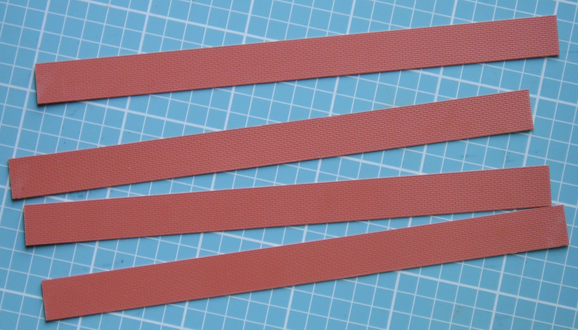
I cut a number of strips from the Staters Brickwork sheet I had left over from the Bomen station build.  The Wagga platform face is straight, and not reverse stepped like most NSW platforms.  This makes the Wagga platform easier than otherwise - probably the only win to save time in the entre build. 

The track in front of the station will be added when needed for the diorama.  This is so that when fitting the station on the layout, I won't have the problem with track, if I need to later remove just the station.  Thinking ahead?   Masking tape used to contain the ballast on the strip of wood used for the track. 

Ballasting done in the normal way - with the masking tape to prevent unwanted spillages.  The bubblewrap was just in case the glue ran onto the support table.

Wagga station in the late afternoon, picture taken from the footbridge (shadow)


Parcel Office from the platform.  The blue luggage carts are courtesy of Ross Balderson, as he included these as a space filler on the etched brass fret for the Wagga station verandas.  The platform face was attached to the wood base of the station with spray adhesive, and weathered with Tamiya Smoke, but could be weathered further.  The platform road is just placed in position

The parcel office from the roadside.  The downpipe on the main station toilet extension is visible

The main toilet block has an unusual window style.  I had assumed the horizontal "bars" were shutters, but closer inspection, the bars are actually metal bars, with a wooden blind behind.

Both roadside, and platform side windows made from strip and rod styrene on 0.020 styrene sheet, backed onto clear styrene "glass".  I won't kid you, these took ages to make, 

The bars are difficult to see in this platform side angle (the roadside image at the front of the blogpost, shows them better) Platform brickwork not yet weathered

Westedge 3D figures, (reviewed in AMRM Dec 2022).  I am always looking to save some time, and preprinted in colour figures may enhance the diorama.  Unfortunately, the glinting on the clothing is distracting, but I hope that Dullcoat will fix this.


At what point do I stop this process?  A lot of years have passed since I was given some advice.  "Twelfth Street Yard", the American layout for the ACT Model Railway Society had been on the exhibition scene for about 5 years, yet I continued to champion adding more and more details, as my thinking at the time, was that the viewing public needed to be rewarded the closer they looked.  Then, my view was countered.  The person said that '12th Street' was already detailed enough, and I would be better spending effort on a new layout.  And they were correct.  The ACT model railway society had 2 other layouts, and I moved towards detailing, and improving "Little Austria", a module HOe layout.  "Yendys" was at that stage, started, but not actively being worked on.

I am close to reaching the sufficient "detailing" for Wagga station.  Yes, there are a few more downpipes to add, small signs to make, lamps, and positioning seats, litter bins, & passengers.  I know there is more that could be done, like a waiting room interior.  However, to continue with Wagga would delay other projects that I am itching to progress and share...


-----

Times are changing.  It is important to record now, what might change tomorrow.  Some examples

Edmonston Street Bridge


I took these pictures in September (and this bridge was the subject of an earlier blog-post)


These two pictures taken last Tuesday (Nov 29, 2022), showing the collapsed retaining wall, due to the heavy rain Wagga received in November.  Unsure if this will be repaired, as the bridge has to be removed for Inland Rail in 2024? - and it may be possible for this replacement bridge to be advanced


Harefield Shuttle

One of the regular trains that I watched (and listened too) was the Visy Harefield shuttle.  Their normal motive power was vintage Goodwin Alco engines - and the burble from their engines was quite distinctive from the GM,  GE, and chinese built locos.

Well, Visy relocated their intermodal operation from Harefield to Bomen's new intermodel facility on Nov 24, 2022.  This reduces the round trip truck haulage from the Visy factory in Tumut by about 30km, and allows Visy to run heavier trucks.  The Bomen operation also means that complete trains can now run direct to and from Bomen, and the breakup of trains at Junee for the shorter Harefield siding is also not required.  The Alcos are still running light from Junee, to Bomen, as they are needed with shunting at Bomen.  

I failed to take enough pictures, but there are u-tube videos of the shuttle in its heyday.

In 2018, the shuttle departs Harefield (silo in background) in the gloom of the  late afternoon.  Alco smoke a feature.  As a passenger in the car, I wasn't able to stop.


Finally

If I don't write another blog post in the meantime, may you all be safe for the upcoming Holiday period, and hope that you are able to get some quality time.  

Wednesday, 14 September 2022

Edmondson Street Bridge

 Edmondson Street Road bridge - photo diary

One of the bridges that has to be replaced prior to double stacking by Inland rail project, is the Edmondson Street bridge.

In 1995, a Fearnes Wagga bus crosses the bridge.  This is the view looking west, towards Albury

The bridge is on the western end of Wagga's station.  Earlier this week, whilst waiting for my car to be serviced, I thought I would take a few more photos, of this soon to be replaced bridge.


Western side of the bridge, as viewed from the Cassidy Footbridge, in 2016.  Close look at the central pier shows an interesting feature

Another picture from 2016. The security fence prevents access to the line.

The fence also makes picture taking awkward.  This picture from last monday shows part of the fence, as the camera is raised well above ones head. The central pier shows that it might have been extended

Cribbed retaining wall has built up the roadway

Some of the graffitti from 2016, is still present in 2022.  Note the different coloured brickwork where the wing retaining wall changes from a slope, to vertical.  More evidence that the roadway has been widened in the past

Cribbed retailing wall stretches down the hill towards Edward Street (Sturt Highway).  The slope of the roadway is planned to be increased for the new replacement bridge - causing some community concerns.

A 1949 picture of a water tank, and alkali plant, located just west of the bridge.  I do not know when this was removed.  But there is evidence if you look closely. 

A pair of water pipes can just been seen poking above the grass.  The shadow of the bridge railing can be seen on the track.  The fence at the back is the boundary to Mount Erin school.

The roadway, as viewed from the Edward Street intersection.  

The pedestrian railing is quite simple

Lineside poles have the wires going over the road, rather than through the bridge

Access to the bridge is much harder in 2022, than even 2016


View from  "Mothers Bridge" footbridge - looking west.  Note the offcenter pier

From what I can determine, the bridge was built to replace an earlier level crossing approx 1940.  It was originally just a 2 lane bridge, and later widened to 4 lanes with the growth of Wagga Wagga,  south of the railway line - and I dimly remember this happening in the 1960s.  The construction is typical NSW, with sloping wing walls.  The deck is re-inforced concrete, over some shallow steel beams. 

I plan to include a model of this bridge on my layout, but won't have the space for a full roadway ramp.

In 2012, A preserved Southern Aurora passes under the roadbridge on the main line, rather than the platform loop.  Picture from the internet

Inland Rail
As mentioned before, the bridge is planned to be replaced.  Below is the artist impression of the new bridge, as seen on Inland Rail's website

The gradient for the footpath from Edward Street is too steep to meet modern regulations, so there is a zig-zag provided on the station side.  


Some bonus pictures (if you have got this far)


A Junee bound Pacific National wheat train approaches Marrar, on the Junee-Narrandera line on August 18th.  The canola fields are bright yellow.  The road is the Canola Way, and well worth the detour if you are travelling to Adelaide via the Hume/Sturt Hwy

Another classic streamliner at Junee - GM27 last August.  Same spot as 4204 last month.  This one has been also saved from the scrappers, but has been refurbished/rebuilt for SSR (Southern Shorthaul Railroad) freight train operators


Saturday, 6 January 2018

Murrumbidgee River bridge – part 4 – Track


Compromises are something we all have to deal with .  On a model railway, almost every decision is a choice between alternatives,  and  there is a trade-off between speed of construction, the size of the layout,  materials used, money spent, and satisfaction of the finished product.

Murrumbidgee river at low flow levels. Note the weathering effect of the river on the piers.

The Murrumbidgee River bridge is a model where I have tried to push my own modelling standards, at the expense of money spent, and time.  I am fortunate that I am not up to my armpits on actually building the layout proper at the moment, as the goal  to get trains running would have me working on other tasks.  The layout room build is still some way off. 

Even so, I am glad that my bridge model is not full length, as the construction of the shortened version  has become  a marathon.  The end is in sight.

The trackbed of the real bridge consisted of 2  metal girders running the full length of each span.  Sleepers laid across the top of these 2  girders.  The Uneek kit supplies 2 thin stripwood lengths to substitute for the lengthwise girders.  The assumption,  although not stated in the Uneek instructions, is that one will use flextrack for the bridge track.  Simple and quick.  Well, this was a compromise that I wasn’t going to take.  It looks wrong

I lacked measurements of the lengthwise girders, although my own detail photos gave a hint of the size.  I also needed to maintain the “loading gauge” clearances for locos and rolling stock, so they couldn’t be too thick.

 I checked the Greg Edwards data sheets (sheet P13) to get some ideas of the measurements on unballasted bridge decks.  The sleepers are spaced about 11mm apart for HO (just under 3 scale feet), and the sleepers are longer than sleeper length on ballasted track   Searching my supplies, I re-discovered a Campbell’s packet of 500 bridge and trestle ties, and rather than make yet another pair of metal girders, I thought the 10” square North Eastern stripwood would work.

Eight lengths of 10” square stripwood were painted grimy black to match the colour of the bridge spans.  Calculations showed just over 200 sleepers were needed.  I painted these sleepers white in batches over a few days.
Some of the timber after painting. I have decided to go with a full white sleeper, rather than just painting the tips. This may be a mistake (or own goal), but it is my layout, staining the sleepers first would have added yet more time to the project, and I am building the bridge for me.

Adding the sleepers to the span.  I found it easier to measure 88 mm (7 sleepers worth), and flue down one sleeper.  When this was dry, I would then halve the gap, etc, until 8 sleeprers were in place.

After the first base made, the spacing could be transfered to the second, third and fourth.


Fitting the sleepers to the girders is as pictured.  Make sure that everything is as square as possible.  I am using PVA glue as the adhesive.   I am also building this on a sheet of glass, to stop any twists, and bumps

The rail is stripped from Peco SL100X flex track   Yes, Code 100 – which is yet another compromise.  My experience with code 100 in the past with “12th Street Yard”, and “Yendys”  has been fairly positive, provided the rail is painted.  Removal of the shine on the sides of the rail is the key to hiding the rail height.   On the forementioned layouts, I sprayed Floquil “Roof Brown” on the track – including the sleepers, cleaned paint off the railhead, and ballasted afterwards.  Spraying the rail once it was down on my bridge isn’t possible, so the rail has to be painted   first.

Having observed handlaid track on many layouts, both in Australia and in the USA, shows that it is spiked directly to the sleeper base.  But to my eyes,  it doesn’t look right.  Something is missing?  Have you noticed?  Every wooden sleeper should have a pair of tie plates, that hold the rail in position.


The tie-plate pictured is 20 cm x 30cm in size.  In HO, this is around 2.3mm x 3.5mm.  As the peco code 100 rail track base is marginally wider than scale, I thought I would go with 2mm x 4mm.  I thought about many methods to simulate this on the sleeper.  In the end, I painted  Floquil roof brown onto white paper, sliced off a 2mm strip, and chopped the strip into 4mm lengths.    I have placed no other detail on them.  A spot of glue on the sleeper, and place the paper tie plate in roughly the right position, adjust, and wait for the glue to dry.   Hint, use the tip of a sharp knife (I used a #11 surgical scalpel blade) to spear the paper, and then move it to the glue spot.  The glue will pull the paper off the knife tip, and the knife tip can then align the paper.

Paper tieplates added to the sleepers

The track to the right has the tieplate detail, to the right without for a direct comparison. . Make up your own mind to whether this detail is worth the effort?

I thought I would see if the effect is worth the time and effort.  It is subtle, but I do like it.  What is also apparent, is that the tie plates are not consistently positioned on the sleepers.  I will have to adjust my technique in the future, as the viaduct track will not be hidden by the bridge girders. 

Rather than spiking the rail to the sleepers, I used Techgrip Polyurethane  adhesive I bought from Bunnings, and smeared it on the rail underside. With  track gauges to hold the rail at the correct gauge,  apply weight.  The glue goes off slowly, allowing fine adjustments in the first 15 minutes .  Important to try and  get the new track centered exactly over the sleepers.


Checkrails.  I have always thought that raill bridges should have checkrails, but the end view of the cut-up bridge at Wagga only shows the main running rails.  However, I was sent a picture of the Whitten truss bridge at Woolbrook, and it has checkrails.  

Woolbrook Whitton Truss bridge - single span.  the checkrails positioning does not follow the Greg Edwards Data sheet, so this pattern won't be followed

Interestingly, the rail appears to be spiked directly onto the sleepers, with no tie-plates.  This is good, as that means that the check rail will be slightly lower than my running rails, so they may not lose the paint during track cleaning.. The check rails were painted, bent to shape, and glued  between the main running rails

Attach the track base girders to the Whitton truss with adhesive.  In this case I used PVA glue.  The glue takes a few minutes to go off, which allows for adjustment, but also if I ever need to remove the bridge deck, then the glue can be pulled apart without undue damage to the bridge deck or the bridge. Again, make sure the rail is centered. This is the last chance to get this right  

The bridge deck extends onto the future viaduct.  

Fishplates are there as a aligning point, where the bridge spans meet.  I have another sleeper (not shown) to fit under the fishplate when the bridge is finally installed  on the layout

I have fitted  fishplates to the end of one bridge span, as I want to be able to separate both spans for storage.    My goal with this series of Blog Posts was  to complete the 2 main spans, and lay track.  Actual installation on the layout is in the future, as the process to create my train room out of half my garage is ongoing.  Decisions on the river depth will then be made, installation and weathering of the plaster piers, as well as the construction of some of the connected viaduct.

It was 43 degrees C outside, and a wind blowing in Junee, so I took these pictures inside. The plaster piers have been painted since the initial part 1 blogpost, and they are just holding the bridge up by gravity.  The "Adelaide" paddlesteamer was built by the late Fred Gill MMR, and whilst well out of time period, it seemed too nice a model to not use.

Some colour at the end.  Loco and carriages all fit under the overhead girder sections.  Whew!!,


Until next time,  build a model or two.  Happy modelling