Sunday 30 December 2018

Kyeamba Bridge diorama fascia


A short update this time – the holiday season makes a mockery of my time management, and coupled with a week of unseasonal 40+  degree temperatures, and biting “stable” flies, https://en.wikipedia.org/wiki/Stable_fly
has limited the time I have been able to spend in the garage.    So, I have about an hour, prior to 9am about every other day.


3801, doing a run-around move, approaches the Best Street road overbridge

 
The Wagga station footbridge is a keen location for train spotting.  3801 has left part of her train of what remained of the Wagga sidings after CTC was introduced.  These pictures were taken in the 1990s.  A steam tour train is rare in Wagga, but a special event will add much interest to my future operation sessions, as well as giving me an excuse to run models that do not fit the 1970 timetable running period 


The Kyeamba Creek diorama will eventually be located on the layout’s upper deck, immediately coming off the helix.  As I have mentioned before, my intention is to limit the width of the upper deck to the area essentially within the railway boundary fences.  Coupled with the increased viewing height, the lack of layout width will be less evident.  But I couldn’t avoid the need of a fascia board.
Besides covering up all the white foam, the fascia needed to be deep enough to hide the layout supports, any underneath wiring, and a series of lights, which will hopefully eliminate the shadows on the lower deck
The first step was to make a cardboard template of the topology on the layout edge.  I did this with some thin cardboard, and a graphite pencil.  Cutting the template out with scissors, and transferring the resultant shape to my 3mm MDF.    A jig saw makes short work of the MDF. 

Cardboard template after cutting


Fitting the MDF to the timber base showed up areas of protruding white foam, which was removed with saw, and sander.  The MDF was then attached to the diorama with wood screws.  A further check showed areas where the fascia top needed some fine tuning with the jig saw.

As my MDF sheet was 600 mm long, I needed two sections of fascia.  Yes, poor woodworking has also introduced a gap between both sections – filler, and paint will fix this once the diorama is installed.   Note, I have NOT done a fascia board for the rear – this side won’t be seen, and the backdrop will go there.

Fascia board screwed onto the diorama.  It extends lower down so the workbench woodwork is covered


Whilst Junee is quite a dry climate, I need to paint the fascia before too long to stop it warping over the 20 year anticipated life of the layout.  I probably should have done this before cutting it to shape, but I am a bit impatient.  But what colour should I paint it?  I have seen some nice green facias, but I think a buff colour might be more suited.  The research continues.


Some extra scenery work has been performed on the unnamed creek bed.  Some 10mm long static grass has been applied (poorly – I am a beginner with this technique), and a quantity of sand added.  Plus a few branches littering the creek bed  from an earlier storm event   Soaked down with PVA glue/water/isopropanol .    It isn’t quite the effect I was hoping for,  but a good base for more tinkering. 
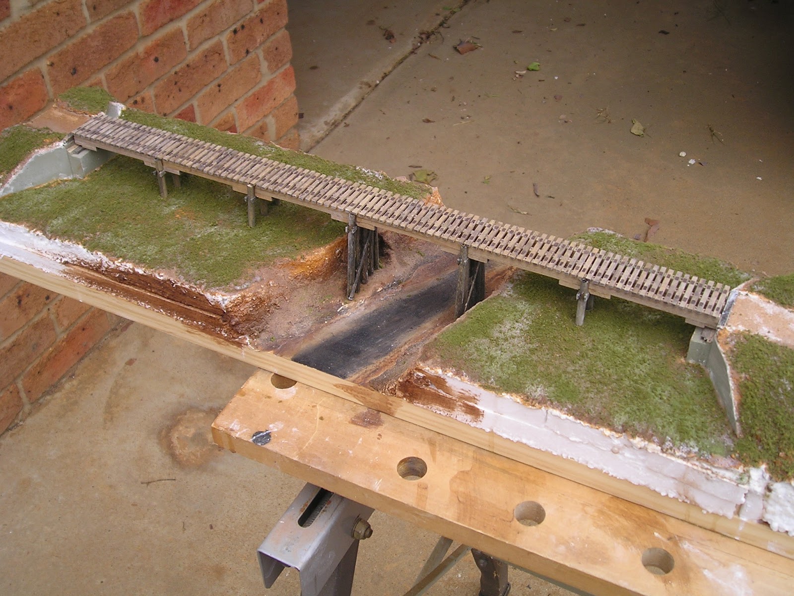
The unnamed creek bed no longer looks like a road, but there is a bit too much grass showing through, and I didn't get the sand drift colour that I hoped I would.  May be only a matter of another dusting of sand over the creekbed?  A bit more ground foam has been added to the banks too.   I am really close to permanently installing the bridge. 


All the best for the new year.

Tuesday 11 December 2018

Kyeamba Creek - Scenery 1


Kyeamba Creek Bridge – Scenery

Trying something new could be the title of this post.  Finally made a start on the scenery.


Unnamed creek bridge on its new piers

Unnamed creek bridge floats above the baseboard between its pair of timber abutments  


Timber blocks added to support the bridge piers

 
Polystyrene fitted to the unnamed creek bridge area.  Note the abundance of foam for the embankments
First layer of foam for the main creek trestle.  The embankment foam has been cut, and roughly shaped in this view.

I used white polystyrene, primarily because I had it on hand.  It is not the most pleasant of material to work with.  Hot wire cutters could be used to cut and shape the foam, but a knife, saw,  rasp, and sandpaper works too.  Ensure a  vacuum cleaner close at hand to collect the white beads

Unnamed creek bed after sanding.  My intention is to model this  as a dry sandy creek. 


Sculpt-it modelling “plaster” obtained from Office Works.  I had to order this product in, as Wagga’s Office Works does not stock it.  The “plaster” is mostly very fine plant fibre, mixed with dry glue, and possibly some clay.  If I had to say what the plant fibre was, I would guess it is powdered newspaper – anyone who pulped newspaper for the old K-Tel brickette press would have a fair idea of the feel of Sculpt-it once water is applied.  Water is added, and mixed to form either a thick porridge consistency, or with more water for a thick soup. 

Sculpt-it has a grey colour, is workable for around 30 minutes, and has the advantage of little mess (compared with plaster).  

 Once the sculpt-it has dried, I painted the surface with "raw sienna" artist tube paint.  The effect might be effective in a desert, but it is just the first pass.  The sandy creek bottom has been “zip textured” with is a sand coloured plaster sold 30 years ago, sold under the“Tuft” label.  The ZIP texture  technique has been superceded with ground foam, and more recently static grass, but it still has its uses

 Kyeamba Creek also received the "raw sienna" paint I also used some "burnt umber" for the banks of the creek, and black to represent the water.   What I didn’t show in this picture was that I goofed with the width of the creek, and my first attempt to reinstate the trestle bridge failed, as the banks were preventing the bridge pier to go down.  Another nice aspect of the sculpt-it, was once dampened, it is easy to carve – unlike plaster

Both bridges.  This is the side that won't be seen when they are installed in the layout


I have been a fan of Luke Towan’s scenery you-tube videos, and Luke likes to texture the ground surface with a combination of dry dirt, and tan grout.  I followed his recipe with the red decomposed granite that I had left over from the outdoor landscaping, and I ended up with a pleasant “topsoil” colour.  This was applied over diluted white glue that had been painted over the “raw sienna” painted surface.

The sifted dirt adds another layer of texture - the original paint is just peeking through


Finally some greenery – courtesy of some Faller ground foam.  Even just one colour brings things to life.  The foam was dusted onto diluted white glue that had been painted over the surface.  In my enthusiasm to take a picture, the glue had not quite dried.

Next steps are to fill the dry creek bed with some sand drifts to take away the roadway look, continue filling out the ground, and creek banks with more green, clean up and disguise any white bits showing, add an MDF side to hide the exposed foam, think about the water, plant lots of trees and bushes, and get the track down, and ballasted. 


I wish all a happy, and safe Christmas.  May all your surprises be pleasant


Sunday 25 November 2018

Scooter's Bridge

A few months ago, I was contacted by “Scooter”.  Scooter informed me that he once lived in the Wagga area, and had constructed a HO scale model of a small bridge on the line just east of the Wagga RAAF base.  Scooter has now moved to Western Australia, and no longer modelling NSW HO.  He offered me his model, as he thought  it would be better on my layout, than languishing in a drawer.


Worse for wear, the rail bridge is visible from the Sturt Highway just east of Forest Hill
This small bridge is located in a field, and visible from the Sturt Highway.   I searched my slides taken in the 1980s, and 90s, and disappointingly, I could not find any of the bridge.  Fortunately, the bridge still exists.
So armed with a high zoom camera, I traveled along the Sturt Highway.  The bridge is located on private land, and trespassing to get closer would not be appreciated by the farmer.


The camera was at x 36  zoom, and I used a fence post to stabilise the picture, but there are some optical distortions that make the bridge look even worse than it currently is. . The wing abutments had eroded in the 30 years since the last train.

View from O'Hehirs Road.  Note the 2 piers - one is 3 posts, the other is 5. As the height of each pier is the same, I really don't know why there is a difference
Another picture from O'Hehirs Road.  The telephoto effect makes the 42' of bridge look like a small culvert. What is obvious is that the line dips down to the bridge, and there are no checkrails

The bridge has 2 piers, and three 14’ openings.  What I did find unusual, was that the two piers have a different construction – one having 3 piles, and the other 5.   I don’t see any photographic evidence of bolt holes on the angled bracing to indicate that the missing 2 piles were ever there.  The abutments have heavily eroded.    My picture taken from O’Hehirs road also show no checkrails

Scooters bridge model arrived in the mail, and I was extremely pleased.  The detail work is brilliant, and it is great to see an alternate approach to building a trestle bridge.   Scooter has modelled both piers with 5 piles,  and this just adds to the mystery.    I suspect that I will be locating Scooters Bridge on the layout’s lower level, just before the helix.  And the Scooter’s name will be retained – a lot better than “unnamed trestle bridge in a field”

Scooter's model is in far better condition than the prototype. Scooter has added all the sleeper bolts, which makes me think I need to add these to my kyeamba creek trestles


Scooter's models of the wingwalls show what the prototype bridge has lost

Parts loosely assembled.  Compare this shot with my prototype bridge picture taken side-on at the start of this blog post.


Thanks Scooter.  

Sunday 11 November 2018

The un-named creek bridge


Kyeamba Creek Bridge – pt 4 - the unnamed creek

It was really great to get to the Wagga Wagga model train exhibition last weekend, seeing some great layouts,  and even better to renew or make new contacts.


Stockinbingal layout, built by the Wagga Wagga Railway Modellers, and recently restored by Rodney Smith and team, made a welcome reappearance at the November 2018 Wagga Wagga model rail exhibition.  This layout was featured in AMRM, and AJMR almost 2 decades ago.


  The Tumba Rail group had a stand, and their brilliant display of pictures on the Tumbarumba branch never fails to inspire.  Mark Pottie (Tumba Rail) advises that he is planning a new booklet with more pictures of the branch to Tumbarumba, including the stockyard siding at Ladysmith.   I also received valuable information, including a picture, and mudmap of the Humula sawmill.    During the weekend,  I had an unexpected visit to my home in Junee, by Peter Beyer (“Branching out NSWGR” blog). Peter gave me  one of his shapeways printed toilet block for Tumbarumba.  Fantastic detail.  The model will still need to be finished, but I have a few projects to do first – one of them is the Kyeamba Creek Bridge

All the piers are now attached.  Only the longer ones are touching the wooden base.  I have also added the tie plates to the bridge sleepers, in a similar fashion to my earlier effort on the Murrumbidgee River Bridge

Addition of painted rail, shows how the Peco code 100 track will connect.  The Peco sleeper base will need to be painted too, as it looks far too plastic.  Ballasting will also help.  But I am still unsure if I will use code 100 rail, or opt for a finer code 70.  If I choose the latter, I will handlay instead of using Peco.

The bridge, and the rail have not been secured - as it will be easier to detail the scenery under the bridge if the bridge isn't there


As I indicated at the end of the last Blog, I had a lot of repetition on the Kyeamba Creek bridge.  Well, I am happy to report that the bridge is now essentially complete – so it was time to move onto the unnamed creek crossing
I have shown this picture before.  The end abutment had been washed away in the 2016 rain event.  This 3 span bridge is around 100 metres away from the Kyeamba Creek bridge, and is good from my modelling viewpoint, as a model of its timber abutments will use the abutments I had in the Ironbark models kit

The third span of the bridge over the unnamed creek was added to the existing 2 spans previously constructed almost 30 years ago.  The extra span needed sleepers, but the original Ironbark Models provided only enough sleepers for 8 spans (6 spans worth of sleepers were used on the Kyeamba Creek bridge).  I had thought that I would raid my supply of NE stripwood for the remaining sleepers, To my dismay, I didn’t have the right size in stock.    Quick inexpensive solution – cut my own from a sheet of scrap basswood.   

The basswood sheet is sliced into sleeper width strips.  Make sure your knife is extremely sharp, and use multiple passes, and not much pressure. 

Once the strip had been cut to length, I compared my batch with the originals in the kit.  Yes, mine will need to be weathered, but from a dimensional viewpoint, spot on

The abutment construction starts with the attached support pier. 

The end abutment pier was previously constructed.  The timber for the wings was still in the Ironbark models kit, and this was cut to shape using the templates supplied in the kit

The poles were glued to the wing wall timber at the appropriate spacing

The wooden poles were cut to shape.  Note that the wing walls slope slightly inwards, which means shaping the bottom at a slight angle off the vertical
I made a base for the wall sections to attach to.  The 3 sub-assemblies were glued together.  Later I installed a reinforcing block of wood behind the end pier, and wing walls


Now that the abutment was built, I used the 3 spans to determine where the abutment needed to be installed on the board.  Note that the base of the abutment sits above the baseboard (and the creek level), so some extra tweaking of the benchwork support was done to maintain the correct height.  

New and old sleepers to go on the third span.  I am getting happier matching my original weathering.  I had not yet fitted the nut/bolt/washer castings to the wood beams in this picture 

I used the deck of the 3 spans to position the end abutment.  Both abutments are sitting on wood supports, above the wooden board.  The newly made abutment is not finished, but the effect is there.  The 2 intermediate piers are still to be built


Both bridges, but there is more work on the unnamed creek bridge, before it is ready for scenery.  Length of the board is 1.2 metres, and this should be enough diorama for any future branchline train photography


Once I complete the woodwork for the unnamed creek, I will start on the  scenic work.  Only then will I add the bridges,  rail, and ballasting.    This simple project is taking far longer than I would have originally hoped.

Until next time.    

Thursday 18 October 2018

Kyeamba Creek Bridge - 3


Some things just cannot be rushed.  But, distractions aside, I am slowly moving forward  with the Kyeamba creek bridge build. 


In my opinion, the set of drawings done by Ironbark Models are the best ever done for an Australian kit, before, or since. These drawings are printed on glossy foolscap paper, and are remarkable, as the kit was limited to only 250 kits (my serial number is #11). Ironbark models disappeared from the scene shortly after their bridge extension kit hit the market.  I would be interested to know what happened to Ironbark, and how many of their kits were built, or still remain in cupboards, to be rediscovered.  


Building up the concrete “plinth” that supports the ends of the Kyeamba creek bridge timber spans was done with layers of 3mm MDF.  After sanding, this was glued to the abutments, and then painted with Floquil concrete.  A layer of 3mm basswood was then glued to the top of the subroadbed pine.   The wooden timbers were then glued to the top of the plinth, and the top of the abutment.
This subroadbed pine was cut to accommodate the existing timber abutment for the unnamed creek. 

The track embankment between the two bridges. I have already added a section of basswood to bring the height of the embankment up a bit - so the later cork layer will be at the correct (I hope) height
]
After some adjustments,  the base was ready for the Kyeamba bridge deck.

As my recovered bridge deck was only 4 spans, an extra span at each end was added.  I did have some additional stained timber in the Ironbark models kit box, however, this would only give me one span.  For the extras, I used 12” square  North-eastern stripwood.  However, this led to another problem – matching the stain.  For the life of me, I cannot recall what stain I used almost 30 years ago.  The Ironbark kit instructions mentioned a combination of Floquil “driftwood” and “walnut”, not that I had those at the time, or now.  So I made up a concoction myself from thinned down floquil paints, but it didn’t really match.  As my bridge will be viewed from one side only, I used my older stained  timbers on the viewing side, and the newer mis-stained timber on the other side.
The two bridge decks, after adding the extra spans


Some trimming of the bridge timbers to fit the gap between abutments, and time to start on the detailing
Due to a glitch with my measuring, the Kyeamba creek bridge ended up around 5mm too long to fit between the abutments. I would like to blame the thickness of the MDF, but the reality is that I goofed.  Anyway, both end spans had to be shorted by around 2.5mm - which is about 8 scale inches.  Hopefully it won't affect the appearance too much.  As a sideline, the official railway survey of the line states that the end spans of the Kyeamba trestle bridge, are 14 feet, and not 24 - but my visit, and photos show that this is incorrect.

The kit supplied Grandt line 1” Nut Bolt Washer (NBW) castings. These castings were painted rust, and holes drilled in the bridge deck – top and bottom.  Whilst fiddly, it actually doesn’t take a huge amount of time.  Good lighting, steady hand, comfy chair, and good music to listen to is suggested. My method is to fit a 0.6mm drill bit into an Archimedes pin vice drill, and a few seconds later, the hole is made.   After making half a dozen holes, transfer some PVA glue on the point of an ordinary pin to the hole.  Hint. I use the point of the pin to make the hole entrance slightly larger, and this also leaves a ring of glue around the hole entrance.   I use tweezers to transfer the casting.  Push the casting home, and the glue dries. Repeat the process until all NBW are installed

Bottom of the span.  Note the rebates in the corbels for the piers

Top of the span, also showing the Grandt Line NBW castings. The original plastic colour is black.

Sleepers are glued into the spaces between the NBW castings

The sleeper spacing is every 5mm - so getting the NBW castings drilled into the timber at the right spacing is fairly important.  Even so, there is still a lot of variation in my done by hand drilling.


New timber piers were made.  Again, I did not have enough stained timber to make all the new piers, and it was not possible to disassemble the exiting piers, as they were already cut for the now incorrect cross bracing.  
I raided my supply of timber, and found some dowels (OK meat skewers) of almost the correct scale 12”  diameter .  These were distressed with the saw blade, and then stained using a different method, which worked really well,  far better than my original staining method.  I may have to re-stain my original bridge  timbers to match.

The deck was again fitted between the abutments, and measurements taken for the 2 main piers that will attach to the timber base.  Shaping and fitting the piers into the jig was the easy part – cutting out the slots for the cross bracing was not.  Fortunately, the Kyeamba bridge only has cross bracing on 2 piers.
The central timber piers are 61mm high.  I have started to cut the rebate into the pier for the top chord.  The angle brace rebate is still to be cut.  Once one side is done, remove the assembly, and rebate the other side.  This is not easy, and I understand why it is easier to simply glue wood together to get the shape.  The weathering of the dowel has exceeded my expectations, and looks old and weather beaten - after all, the piles were installed for almost 100 years when I photographed the bridge, and have survived floods, and insect attacks.  


After completion of the pier, which included fitting yet more NBW castings to each joint, the pier was installed onto the bridge deck, returned to the bridge abutment base, and checked.  All OK, the pier was glued. 
 
One pier down, 4 more to go.  The peco track on the embankment has been put on some cork to check the transition from plastic sleepers to wood.  My original idea was to use code 100 rail for the entire layout, but I may substitute code 70 on the bridge area, and hand-lay the small area of the embankment with wooden sleepers.

 
There is much repetition now for the next lot of piers.  Then I have the unnamed creek trestle to finish, followed by the landscaping.  I keep telling myself this is a hobby.


Stay sane, build a model.