The Broadway museum
layout
The Bethungra Loop, is a railway deviation, built in the 1940s, to ease the gradient up Bethungra Hill, and eliminate the need for banking engines. The loop is located within Junee Shire. The Broadway Museum in Junee contains historical items associated with the town, and shire, so it was not unexpected, that Junee, being a railway town, would have a number of railway exhibits. One of them was a layout depicting the Bethungra loop.
 |
| A NSWGR staged publicity photo of 3 trains on the loop. |
 |
| Map of the loop, showing the rail deviation. From a tourist viewpoint, there is little information about the railway. All 3 elevations are visible from the Olympic Way road, but that is it. Having seen the informative displays on the side of the Trans Canada Highway, of the famous spiral tunnels, the Bethungra loop is an opportunity lost |
Many years ago, the guys from the Canberra-Monaro N scale group advised me of this layout. They challenged me to rebuild it.
The layout was an attempt to portray the Bethungra Loop in N
scale. The layout was permanently
installed in a room within the Museum.
The trackplan was not a bad representation of the loop, and the scenery
could be described as sweeping.
Unfortunately, the builder of the layout had passed away before
completion, and coupled with very poor benchwork and tracklaying, the layout
was non operational. The scenery was
also incomplete.
 |
| Some pictures showing the original Bethungra Loop layout located in the Junee Broadway Museum. Whilst incomplete, the possibilities of a great display were there. The backdrops for instance were excellent. Whilst the trees, and the track were saved when the layout was demolished, I am not sure what happened to the backscenes, as I could reuse them on my rebuild of the replacement layout. |
There was another problem.
The room it was located in needed a lot of work – there was a water
leak, plaster was cracking, and falling off, the floor boards were loose.
Anyway, to cut a long story short, the museum eventually
decided that the layout could not be saved, whilst the room was repaired. The layout
was dismantled. Some of the track
was recovered, along with the trees, but most ended up as landfill. Once the room was ready, a number of small
display cases, displaying railway items, were installed. A space was left for a small replacement
layout, again of Bethungra Loop, but the replacement layout also proved
unsatisfactory.
My standing offer to assist was accepted.
The replacement layout was moved
to my garage, and is now taking up residence in my future train space
 |
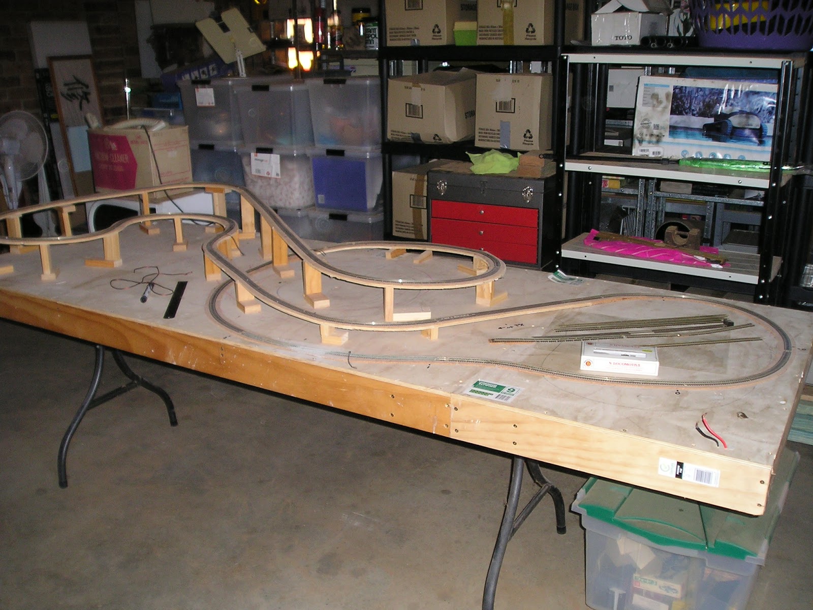
| The replacement layout on a table |
Inspection
As there was no scenery, the inspection was straight
forward. In short, the gradients were
too steep, some of the curves too tight,
the loop didn’t look right, electrics poor, and the trackwork marginal,
with kinks, and some fishplates not seated correctly.
I discussed my plans with Bob from the Broadway Museum, and
he confirmed the problems, and accepted that an extension was needed to better
depict the loop. Bob also said that they
should be able to rework the display cabinets within the Museum to accommodate
the slightly increased size of layout.
Bob also handed me some of the N scale track that had been on the
original layout – track pins still attached.
 |
| Some of the track from the original layout. It was originally laid on balsa, and when pulled up, took the balsa with the trackpins |
 |
| After depinning, and straightening, it looked much better |
Reusing track.
Track that had been used before, is not something that is
desirable for an exhibition layout, and certainly not generally suitable for a
layout in a museum context. But I did
not have a budget from the museum to purchase new track, and I certainly did
not have enough N scale track in my own accumulations.
After removing all the track pins from the flex track, I examined
each section closely . Things to look for
1)
Kinks – vertical and horizontal
2)
Sleepers that had been pulled off the bottom of
the rail
3)
Corrosion of the rail
4)
Sleepers that had become brittle, or were
distorted
5)
Brand of track.
In many cases it was possible to snip off the offending
pieces of plastic sleeper base, and slide the remaining sleepers to cover the gap. Serious kinks and corrosion of the rail were
cut out and discarded, leaving 2 shorter lengths of flex track. I also discovered 2 different types of Peco N scale,
and a number of lengths of Atlas in use.
Ideally, best not to mix-n-match track types.
Stage 1. Gradient
The first step was to fix the gradient problem. The trackbed, and supports had been
nailgunned to the plywood base, which was not ideal. Each trackbed section had been buttjoined to the next on top of the vertical
supports – introducing vertical kinks in the track. This is not something that I wanted to
repeat. It wasn’t all bad. The
geometry of the spiral was OK (the curves were a bit tight, but I was
assured the train got around the spiral’s curves OK), and the “down track”
grade was a consistent 3%, so I was able to retain some of the original layout
 |
| Track removed |
 |
| After the supports were removed, the trackbed was kept for re-use |
The track on all except the “down track” was pulled up,
followed by the plywood roadbed. The uprights were extracted with a hammer. The
uprights cannot be reused as they were full of nail gun nails
Additional plywood pieces were cut for a longer ramp for the
“up track”. These and the original plywood
sections were joined together to form a single piece of roadbed.
Fitting new supports enabled a rising grade of 2 to 2.6% for
the “up track”, allowing a 4cm vertical height gain for the spiral. This doesn’t allow me to have the prototype’s
deep cutting between the 2 tunnels, but compromises have to be made.
 |
| I cut a series of uprights with the drop saw. The number represents the height in cm |
Stage 2. Cork
3mm thick cork was glued to the new trackbed pieces, and all
the cork was then sanded smooth.
 |
| Not the best picture, but it shows how I joined the sections of roadbed together - using scrap plywood. I also used laid the cork double width, as this gives me more flexibility when it comes to relaying the track |
Stage 3. Track
restored to the spiral
When I pulled up the track from the spiral, I had hoped that
the pieces could be reinstalled on the updated roadbed. This proved to be problematic,
as many of the flex track joins were on sharp curves, and I could not get rid
of the inevitable kink at the join. So new sections
of flex track were cut and positioned to avoid joins on sharp curves. And before one asks, I am aware of the
technique of soldering rails together using rail joiners before bending. It is a silly thing to do if you cannot climate
control your layout room, as expansion of rail in the heat, and contraction in
the cold requires gaps at the rail joiners. A lesson learnt from experience
 |
| One of my essential tools for track laying is a mirror. A mirror allows a rail head view, and can pick up kink problems quickly. |
Stage 4. Electrical considerations.
The layout will
operate as an oval, with only one train running in one direction. Fairly simple electrics, but do not rely on rail joiners for carrying the
current. Every section of rail should
have its own connection to the power bus.
I find working under layouts anything but pleasant, so I soldered jumper
wires to the ends of all flex track pieces.
Yes, it may not be visually the best, but once the track is
painted, and ballasted, the brown multistrand wire will almost disappear. To carry the power to the extension, a plug and socket is planned
Stage 5. The bridge benchwork and extension
On the prototype, the “up track”, after negotiating the
spiral, is on the "down" side. To get it
to the correct side, it crosses over the” down track” on a deck plate girder
bridge. (see the aerial view and map at the start of this blogpost) This aspect was missing from
the layout I received, but in my opinion, had to be installed. Re-installation also forces the extension of
the layout onto new benchwork.
Unfortunately, I did not have enough real estate on the original
benchwork to maintain the 3% falling grade of the “down track”, and another
compromise, was to flatten, and then dip the “down track” under the “up
track”. A further compromise is that the
below track plate bridge will need to be changed to a through plate
girder. Once the tracks cross, the “up
track” will descend downwards, whist the “down track” will go back up, both
tracks reaching the same level on the new benchwork.
 |
| New trackbed for the crossover bridge in place, but not yet secured |
My hope is that the scenery will mask these grade changes,
but this is something for the future.
At the time of writing, the roadbed of the down track is not
yet secured to risers.
Stage 6. The new benchwork track plan
As previously mentioned, both the up and the down tracks
will resume their side-by side posture on the new benchwork. At that spot, my hope is that the Olympic Way
level crossing can be modelled. I think
it is important that people visiting the museum
can place themselves in the scene, as many would have crossed that level
crossing on their trip to Junee. After
the level crossing, a balloon loop is planned.
The balloon loop will be left as raw benchwork, and not sceniced, as it
is not part of the Bethungra Loop scene.
I settled on 27cm radius, as this was almost the same as the
peco set track #2 radius pieces I had, approximated the now sharpest curve on
the spiral. Fortunately, it was also about the maximum that I could fit on my
extension benchwork
 |
| I was able to reuse the balsa from the original track as a compass for drawing curves. Here is a 27cm radius |
 |
| Just a mockup of track on the balloon loop. I don't have a lot of N scale models, just a few to test curves, grades and clearances. The size of this board is 1200x600mm. |
Next time.
Connecting the new benchwork to the old, track testing, track painting,
and scenery starts
Whilst many would consider working on an N scale layout, not
of Wagga, is a delaying exercise, I am using it as a welcome distraction. Not
only am I getting back into actually building something, I am also trying out
some ideas that may or may not get used
during the benchwork phase of the Wagga layout.
And as I am scheduled to attend the Canberra “N Scale” convention this
October (10th-13th),
the timing is probably just right.