Intercapital Daylight
One of the regular trains that served Wagga in the 1970 time
period was the Intercapital Daylight. As
the name suggests, this train ran daily between Sydney, and Melbourne during
daylight hours. This pair of trains
started running in 1962, with the opening of the standard gauge from Albury to
Melbourne. The Train consisted of a loco
and a RUB set – steel airconditioned carriages, generally 8 cars in length, but
often longer during holiday periods. Very occassionly, with heavy booking, the
railways would run a second division, 30 minutes later than the main train.
 |
| Southbound Daylight passes under the Best Street Bridge |
The train always was diesel hauled - 42, 421, 43, 44, 45, 422,
442, 80 and finally 81s
Being a joint train between NSW, and Victoria, there were occasional
substitutions of carriages, and motive power – although these were uncommon in
the 1970s
The Sydney bound train arrived (if on time) at Wagga at
1:52pm; and the Melbourne bound train at
3:12pm. I travelled on the Intercapital regularly in
the 1960s, and 70s between Wagga and Sydney, and occassionly down to Melbourne
– taking note of the scenery, and the disappearance of steam. Some of the treats from the buffet was the
toasted ham and cheese sandwiches, and the soft serve tub ice cream one ate
with a wooden “spoon”. Things like this
have made a lasting impression
 |
| Double 44s about to arrive at Wagga's platform road. |
 |
| V/Line G class, and a southern Aurora car add interest to the train. The original goods shed, and crane are visible, which would date the picture around 1988 |
 |
| Stealth 8167 pulls the Daylight over the river flat viaduct. |
 |
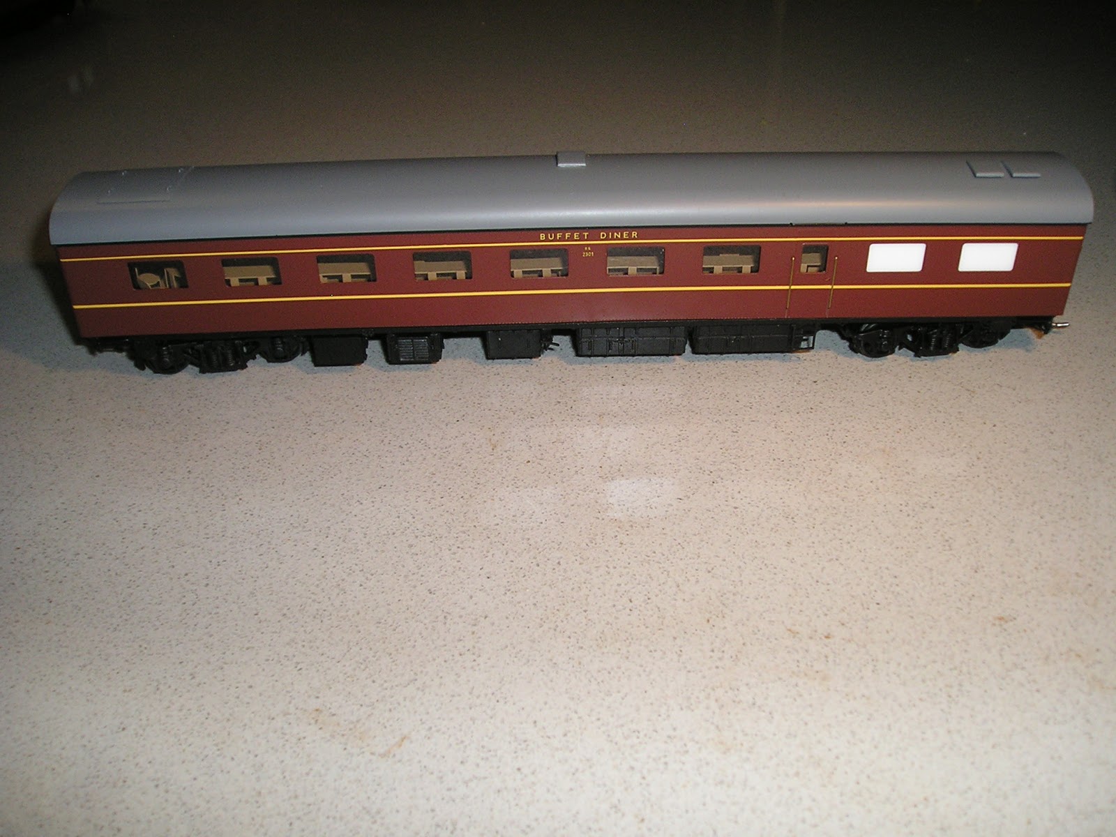
| A V/Line buffet car in the Sydney bound Intercapital Daylight |
 |
| After the introduction of Candy colours, the Intercapital looked like a disjointed collection of carriages. Here it is crossing the Edward Street (Sturt Hwy) bridge. This bridge replaced an earlier level crossing, where the road rose up to the level of the rails, and was the scene of quite a number of fatalities. The bridge was installed around 1979, which is later than my modelling period, so I will be modelling the level crossing |
 |
| Early 1980s, passing under one of Wagga's signal bridge. In my early days of photography, I was using a manual Voitlander camera, with no inbuilt light meter, and it was a fluke to capture a moving train side on without too much bluring. |
 |
| Southbound, near the Fernleigh Road level crossing |
The train was discontinued in August 1991, when two XPT sets
started running between Sydney and Melbourne.
Most of the RUB carriages were sold or scrapped – I remember one
carriage actually making its way to Queanbeyan High School, as the senior’s
common room.
A full history of the Daylight train service can be found in
Chris Banger’s book “Daylight” published by ARHS in 2015
Some extras
Over the years, I have also acquired some interesting material. The below images come from my personal collection
 |
| A staged NSWGR publicity picture of a down RUB set on the Bethungra spiral. The RUB set is pulled by a 45 class, which I think is unusual. Careful study of the goods trains though gives a good clue on what one could marshal on your models |
 |
| Both NSW, and Victoria gave out handouts to passengers on the Intercapital Daylight. These are from different years, and the wording is slightly different. For instance , the later Victorian one is in Metric. The handouts folded out to provide a written commentary on the places, and areas of interest as you travel along the line |

 |
| 2 pages from a much later handout - and possibly better for rail obsessed travellers such as me, as it shows all the connecting lines, and details of openings. Bomen is described as "The Country Killing Center" which is a clue on the meatmorks |
Modelling the Intercapital Daylight Carriages
The RUB set has been a favourite of mine. Over the years, modellers have been blessed
with some wonderful kits and models.
1 - Rails North.
Rails North offered a 6 car RUB set kit in resin in the early 1980s. The windows were real glass, cast into the
resin. I purchased a kit, and sourced
bogies, wheels, and bearings. But my kit
remains unbuilt. I had previously
constructed a similar Rails North HUB set, and the weight of the completed HUB
set taxed the pulling power of my locos
 |
| My Casula Hobbies RUB set, with some extras. The 82 class (Lloyds Kit) would have never pulled the RUB set, but the 40 class (bergs whitmetal) may have. Green engines look great. The carry box was made by Bruce Atrigg at Mittagong. Bruce was also the guy behind the NSWGR turntables that Anton Trains are now selling |
.
- -Casula Hobbies, under the Callipari label,
produced a set of RUB set carriages in injection moulded plastic in the mid
1980s. I acquired 6 carriage kits ( two
first class, four second class), a buffet, and power van. These kits included bogies, and wheels. The kit did not include decals, couplers, or interior. If one wanted flush windows, Lloyds Model
railways had flushglaze packs to fit.
Whilst I was very happy with my assembled RUB set, I did not fit an
interior, or superdetail. The set was
quite light, and I had much pleasure in running it at model rail exhibitions in
the 1980s/90s. These kits are still
available. A great set of modelling
articles by Peter Jarvis on detailing these cars can be found in the pages of
AMRM – issues 241 through 245
 |
| V&T Models - 6 car RUB set in brass |
3 In 1997, Precision Scale Models announced they
were doing a 6 car RUB set in brass, and asked for reservations. John Sargent (PSM) must have received
sufficient interest at $3000 a set, and Samhongsa (Korea) were commissioned to build the models – which
they did. The project then has a
serious setback, (as I was told) John was shocked at the cost to paint the
models – the amount I heard was USD$105 per car. As the Australian exchange rate was woeful at
the time, this represented a cost of about $1200 per set (and more if you also
factor in the sales tax, and import duty payable when the completed models
arrived in Australia – from memory, these government fees added about 20% to the cost) . John was not expecting this extra charge from
Samhongsa, and he walked away from the project and had no further dealings with Samhongsa.
He lost his sizeable deposit. The tale
does have a good ending, as V&F Models stepped up, and the RUB sets were
made available at $5000 a set. (Ref AMRM
December 2001).
4 - Auscision Models are about to introduce the RUB
set, in RTR form. The pilot models look
fantastic, and I have two 8 car sets on order.
Short Review of the Brass RUB set
The Brass RUB set is a model that is extremely rare. In my travels, I have only sighted 2 sets –
the first on an exhibition layout around 2002, when the layout visited
Canberra, and the second, when I was fortunate to win a set on ebay. As there has been no review done, I thought
it might be interesting to see what the state of the art brass was 20 years
ago, a benchmark that the Auscision RUB set models will hopefully exceed.
The set is packaged in a large (possibly too large) sturdy
light green cardboard box, with foam inserts.
There is no label on the box.
There are 6 foam openings for the 5 carriages and the power van. There are 2 first class SBS coaches, 2 second
class SFS coaches, one RH buffet, and one PHS power van.
Initial impression of the carriages is that they are nicely
painted, lining and decals placement is first class. Mine had 140 number on the end of the PHS
van, and a coach – correct number for an Intercapital Daylight RUB. The decals for “Syd end” though are
missing. Glazing is flat, reflective,
with no distortions seen. The underframe
is nicely detailed, and the bogies are quite fine. There is an interior in the coaches, and the
power van is actually powered. Non
functional, scale metal couplers are attached – fortunately, these can be
replaced with Kadees if you operate the coaches. Weight of each coach is between 270 and 293
grams, and they do not roll well – hence the need for the powered powervan. The diaphragms on the corridor connections
between carriages is solid brass, and doesn’t swivel. The wheels to me do not look like RP25/88 –
the flanges are a bit deeper, with a sharper edge than the rounded RP 25
standard. I have no layout to run them
on, so I do not know if that will cause problems later.
Unfortunately, the interior is in my opinion, poorly
done. Samhongsa have painted all the
interiors in a rather bland light brown colour, which neither matches the rich
timber veneered varnish walls of the real cars, or the seat colours. The seats in second class should be a much
darker, and the ones in first class should be green. Whilst the 2+2 bench seating across in Second class, and the 2+1
arrangement in first is modelled, none of the seats have armrests. There is no doorway into the dog-box
compartment. The Buffet car interior is sad. There should be a series of round swivel
chairs close to the centre buffet table, allowing people movement behind the
seat and the wall of the carriage. This is
not done – in fact, it looks like the seats are attached to the wall of the
carriage. Below the centre bench, there
is a series of openings – where on the prototype, this was solid. There is also no urns, sinks, or equipment on
the other bench. Whilst these things
can be fixed by the determined modeller, if I had paid $5000 for the set in
2001, I would have been disappointed. It
is possible that had a pilot model been forwarded to PSM, they would have identified the correct interior paint colours, but I am guessing.


 |
| The PHS power van is actually motorised, and it needs to be, as the RUB set is quite heavy, and doesn't roll very well |

 |
| Both sides of the SFS second class carriage |

 |
| Both sides of the SBS first class carriage. The lack of green seats is obvious |

 |
| Both sides, and underframe of the RH buffet car. There are some subtle differences in thi underframe, compared to the SBS, and SFS cars. |
That leaves me with one big unanswered question. How many sets were made, sold, and where are
they hiding? If any readers have the answer, or even general comments on the sets, I would be grateful if they could post a comment.
I hope to get back into modelling as soon a I clear out the dust in the modelling shed. It has managed to work its way through the smallest of openings, and leave a fine layer over the modelling bench, as well as the floor.
Until then.


