Friday 29 January 2021

More roofing, and a few details

 Wagga Wagga Station Roof progress

It probably goes without comment, but the complexity of scratchbuilding doesn't rise in a linear fashion, with the larger the project - it is more like exponential.  Errors in measurements made at the beginning don't show up until much later, when something doesn't work, or look quite right.  

Wagga station was refurbished, and repainted in 2017.  The concrete rendering over the brickwork had been removed above the awning, giving a clue to the original construction in the 1870s.

At 53cm wide, I am rapidly using up my supply of corrugated styrene sheet, so it is important to minimise the wasteage.  I should have included this on my last blog post.  Below is how I cut the styrene for gable roofs


rearranged.
Picture from last post showing the gable roof in position


The roof truss frame for the eastern wing. The roof trusses are resting on a ring of styrene, which are sized to fit snuggly within the walls.  The tips of the trusses rest on the previously installed guttering strip

Corrugated styrene fitted to the frame, and attached to the gable roof.  Subtle detail - not that obvious from this view, is that there is a channel between the eastern wing roof, and the gable roof.  The roof capping is for the future

The western wing roof was built in much the same way

All the roof is now on. The center section between the 2 gables is just floating, although it also has a styrene positioning strip below the roof frames.  Guttering on the western end hasn't been added yet.

Roof details.

When people view your structures on your model railway, I suspect that the first thing they see is the roof.   So it makes sense to detail it.   

Another view during the refurbishment showing the eastern wing

On the above picture, you will notice the two chimneys, and the roof vent.  Sizes of these, as viewed from the ground are not obvious.  So I did some measurements from the elevation plan I had, and scaled it up to HO.
An early plan, showing the refreshment room proposed expansion (and elimination of one chimney), was itself removed during the 1980s restoration to heritage condition. But it gives the scale of the chimneys and roof vent.


First was the roof vent.  Before I started cutting into my ever dwindling corrugated styrene sheets, I drew a diagram, and made a plain styrene vent to check the fit, and size. Little bit of trigonometry helps with the angles

Roof vent drawing.  All dimensions in mm, not what I scribbled.  I drew the plan 5 times larger than scale HO


Roof vent mockup in the right position


Next was the chimney.  Wagga station has 4 chimneys, 2 are the same, the others vary slightly.  First, draw a diagram

I had to guess one of the dimensions from photos.


The first stage of construction was to build an inner tube from 4 pieces of styrene.  The wide base above the roof line actually happens a bit later 


Cut a hole in the roof to suit the tube.


Insert the tube into the roof.  The construction of the trusses of the roof can be seen from this view

View from above shows the chimney in position. Use of a tube not only useful as a handle during detailing, and painting, the tube provides strength, and allows subtle repositioning to get the chimney vertical.

Next stages are to complete the 4 chimneys, 5 roof vents, the platform gable roof edges, the ridge capping,  the rest of the guttering, and downpipes.  Then the two "extensions" that are visible in the 2 prototype pictures in this blog post.  Painting is then probably going to happen, prior to the awnings and verandas being installed. 

Still managing my new-years resolution for at least 30 minutes a day on the workbench.   Although I had really hoped to have finished the Wagga building well before now.  Until next time. 

Wednesday 13 January 2021

Wagga Wagga station - roof -1

Roofing Wagga station - 1


Western end of Wagga Wagga station.

Looking east. Picture taken from the footbridge

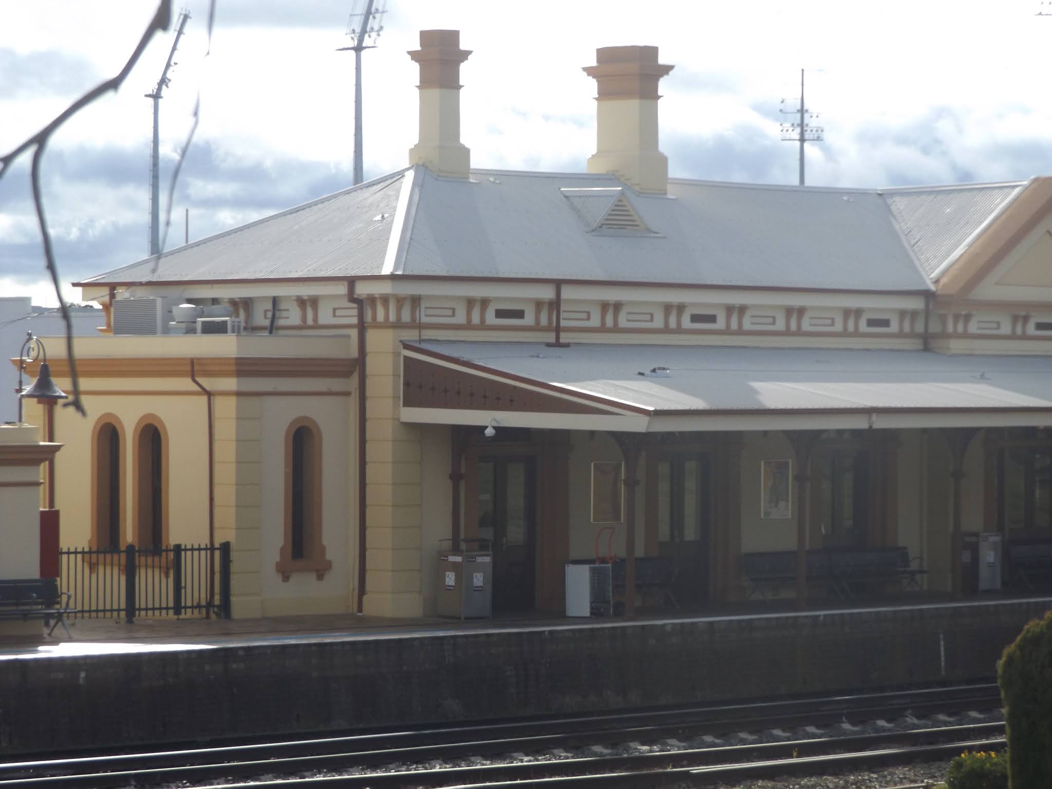
Picture of Wagga station from above. Note the positioning of the chimneys and the size of the satellite buildings. The mainline has been resleepered with concrete, where the platform loop still has wooden sleepers


After the last blog post, I looked at the prototype photos of the roof, and noticed that the trim above the corbels was thicker than the trim on the triangle sections.  So before I did anything, I added some additional styrene strips to bulk this area up to match photographs. 


Pegs make a convenient clamp for the extra styrene. 

I had also thought about guttering.  All of the gutters I had added on my structures up to now, were simply  1.5mm angle styrene strip. Whilst this works, it is mechanically weak.   The Wagga station allowed me to experiment with an alternative, which the below diagram attempts to show


The angled corrugated styrene rests on the gutter strip

The 0.010 x 0.250 styrene strip  was added on top all around the station walls (but not on the triangle sections).  Some 0.010 x 0.040 strip was added to form the guttering in a few places to check out my idea.

The guttering is a prominent detail. I have tried to smooth the join between the two sections of styrene above the corbels - although the camera shows that I was not totally successful in this task

Guttering detail from above


.I thought reinstatement of the North-south triangle sections of roof would be a good first start.  I made up the triangle pieces for the platform wall sections.  After careful measurements, I then fabricated 8 more internal triangle sections (4 on each side).  These triangle sections rest on the guttering 0.010 x 0.250 strip, but leave enough of a gap between the future corrugated iron styrene and the guttering 0.010 x 0.040 strip.  A number of solid beams were then cut, to join the lot together


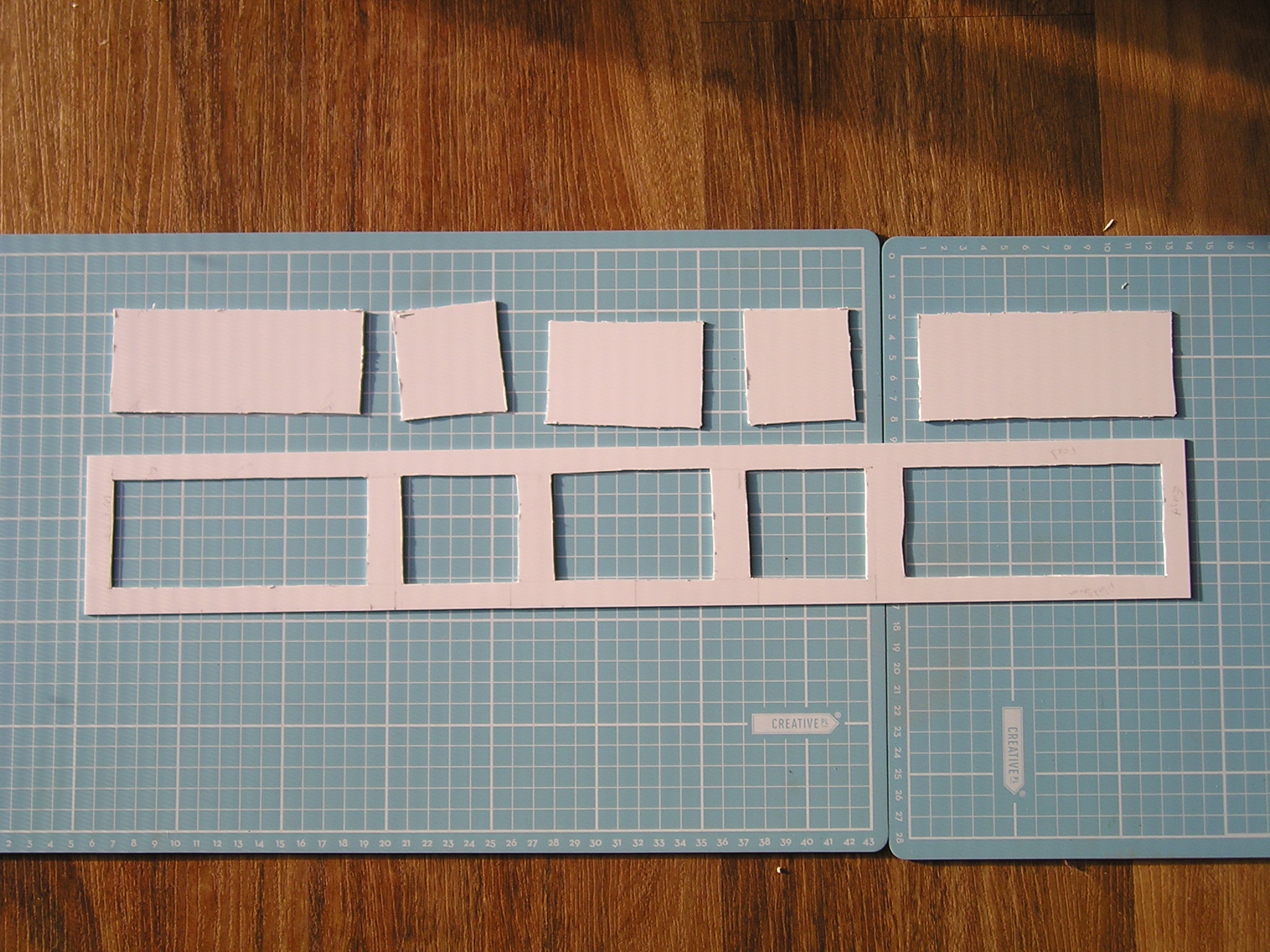
The North-South roof section fits between the triangle wall details.  The smaller intermediate triangle sections were sized to fit on the wide gutter strip as show in the diagram earlier.  The notches in these triangles were cut out with my nibbling tool.  This selection of parts is the first group of two needed


My nibbling tool is a much used tool.  I bought my first one at Tandy (remember that electronics store?), but after it wore out from overuse, a replacement obtained from Jaycar.  Extremely useful for cutting squares in styrene, and thinner sheet brass


The nibbling tool cut a channel into the styrene that was almost exactly 0.080” deep certainly matched my 0.080 x 0.188 styrene strip (the size I also used to bulk up the walls above the corbels). 
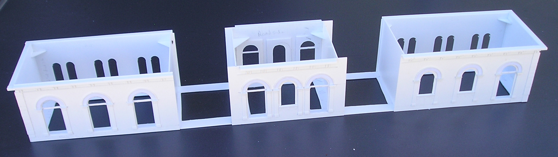
These parts were then fitted in situ on the station.  There is no room for sloppiness here – the roof has to fit snuggly, and the end triangles key the roof into the correct position.  I allowed 24 hrs for the glue to fully harden


Juggling all the angles to get everything square needed a lot of luck, and perserverance. I used two types of Tamiya styrene cement - one was thicker, and allowed for minor repositioning prior to setting - the other type was instant fix. 

After the joints had dried, the assembly was  removed from the station, for measuring up.  Note the rebate in the end triangle areas for the snug fitting of the corrugated styrene.

Adding the corrugated iron was next.  To save material, I didn’t run the full width with the corrugated styrene.  To do so, would have prevented a neat join with the east/west set of roofing iron.  The heavy styrene beams hold the shape well.


The corrugated sytrene was cut into 4 sections, and  was glued to the beams, and end triangles whilst attached to the station. The effect with the guttering is just visible. 

So far, I am pleased with the effect.  However, It is just the first step.  There is still a lot more roof to add.  I have not yet decided if the entire roof will be one section, or if I will have the center section removeable (Which may give me a change to have a detailed interior waiting room).  Then there is the matter of securing the roof to the walls (screwing is the thought) – plus the chimneys.

===============

I am still getting used to the new google blog interface  No longer can I preload all my pictures, and select the ones that I want for insertion in the text.   But it does give better stats.  I noticed that my blog-post on oil depots has now passed 1000 views.  It is 350 views ahead of my next most popular post on the Auscision RUB set.  Maybe these are things people search for in Google?


Trust you have found something of interest in my roof construction approach, particularly with the guttering.  Until next time. 

Sunday 3 January 2021

Wagga Wagga station - Assembling the walls

 Wagga Wagga station construction - Part 5

The only practical new year's resolutions that I hope to continue well into the new year, is to do at least 30 minutes of modelling each day.  Will see how I go.  So far, the effort has been worthwhile


Part of the crowd in 1954 assembled to greet the Queen during her vist to Wagga Wagga. The railways played a good part in running specials, collecting school children from around the Riverina. The coaches stored on the goods sidings gives some idea of the number of trains needed

The Platform side station walls detailing was carried out the same way as the roadside walls.  All were detailed flat on the workbench, and then assembled into sub assemblies.

The eastern end platform side wall.  The two windows were originally doorways, but I had earlier made a decision to model the current heritage design, so I had no choice

Roadside and Platform main entrances were almost mirror images of each other, the roadside has "keystones" which were absent on the platform side.  However, I had assumed that was the only difference. But I was mistaken.

Platform side entrance doors are more spread apart than ....

...the roadside entrance doors which are closer together

This was a whoopsie.  And a close inspection of the plan also shows this.  I pondered a while to think how I could correct the error.  I could not come up with a simple fix.  And I didn't want to construct another wall - So, as the platform side is not visible from normal viewing angles, I simply decided I could live with the error. 

I had cut out a 530x77mm sheet of styrene to fit the base of the station.  To allow for a later access to the roof (I am thinking I will attach the roof with screws), and to give me a source of styrene for the window/door inserts, it made sense to me.

The 3 main subassemblies now glued to the station

On the last blog post, I hinted that I had a problem with the triangle roof ends, in that the walls had warped forcing the triangles out of plumb.  (and I thought these were braced enough to prevent this)  My original idea was that the roof would simply slip behind them.  This wasn't now going to happen.  So, now was the time to take them off, which was a little tricky.  The triangles will now become an integral part of the roof

The large platform arched doorways under construction. 

Now that the station is in one piece, I needed a base to put it on.  This floating floorboard was convenient for now.  The roadside front walls have been attached.  I used sheet styrene for strengthening the 3 subassemblies which you can see in this view

The platform arched sections now attached.

Platform side view from above.  

Next stage will be to add the roof.  I hope this will be a lot faster than the walls 


Just before new year, I went down to the Junee Roundhouse museum, renewing my membership, and purchased the latest A5 booklet on the Tumbarumba branch.  It is titled "Wagga Wagga to Tumbarumba Railway - an era of change".  It has a red cover.  Very similar in style to the earlier booklets by the Tumba Rail group, showing a collection of recently acquired photographs - some I found most interesting from a modelling viewpoint.  I believe the booklet is also available for sale at the ARHS bookshop.

Until next time, build a model or two.