Slide Scanner
I am
pleased to report, that I have finally purchased a new slide to digital
scanner. After some advice, I purchased
a Plustek 8100 from TEDs camera store website on April 13th, and
after 7 weeks, it arrived last week.
It took me
a further 2 hrs to install the software, rapidly read through the manual, and
then came the big test – results on the below picture.
 |
| LVR 5367 taking water in October 1997. The original watering facilities at Wagga were out of use by this date, hence the local fire brigade did the honours |
 |
| Ready to depart |
Of course,
I will need to do more experimentation. It is nowhere near as fast as my cheap
and cheerful scanner, but if the first scans with the Plustek 8100 are anything
to go by, the quality exceeds my earlier Epson scanner, purchased in 2004, and
still attached to the 2004 Dell desktop running Windows XP.
 |
| The plustek scanner |
Enough of
computers. Back to some modelling.
Brass loco repairs
Last
weekend, a number of model train exhibitions, and the NMRA convention had been
cancelled due to the COVID19 situation.
So, instead of spending the whole weekend up in Sydney, I thought I
would use the time to restore a few brass engines I had in a sorry state.
Bergs
C30T
An ebay purchase,
at a discount as the seller said it had some issues. First of all, it didn’t run. And second, was that the body did not sit
correctly on the chassis.
Brass steam
engines are generally easy to take apart, and the Bergs 30T is no exception.
 |
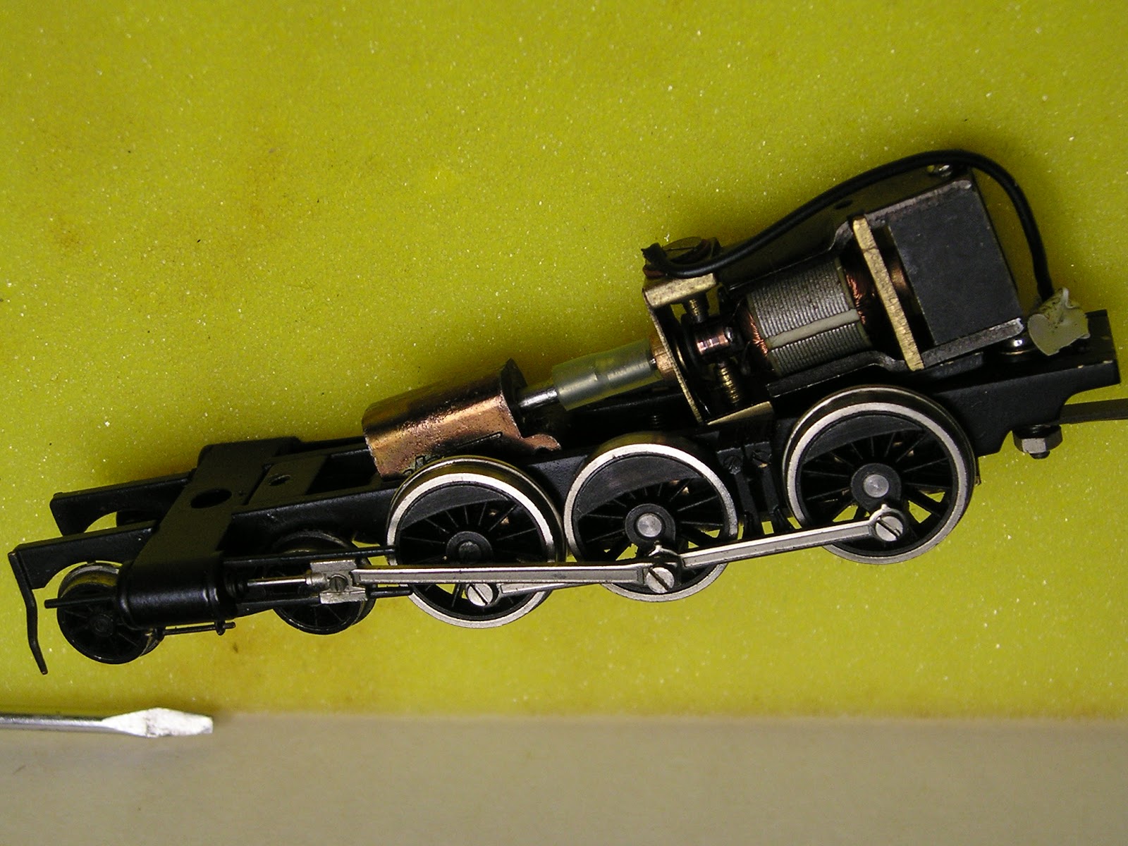
| The inside of the Bergs 30T. The openframe motor uses plunger carbon brushes, and the insulation on the back of the frame is visible |
The first
thing that I noticed was that there was a lot of insulation for the drawbar
pivot wire going to the motor. This was interfering with the body mounting, and
so the second problem was an easy one.
The motor not running fault, is normally caused by a broken wire, but
this was not the case. I unscrewed the
motor, and disconnected the Delrin driveshaft coupling. Applying power directly to the motor
terminals did not fix it. I was
contemplating a can motor upgrade, but I thought I would check the carbon brushes
(plungers). Well, one was worn down past
the point of useful. I fitted a
replacement, and success. Re-assembled,
it looks, and runs OK. Sure, the motor
is on borrowed time, and a can motor upgrade, along with DCC is in its future
 |
| Bergs 30T model was made by Kumata (japan) around 1980. |
The loco
would look better with a bogie tender, and this is where acquisition 2 comes
in.
Bergs
C32
I swapped a
surplus new DJH C32 kit for this one, sight unseen from a mate, who said apart
from the lack of box, it was a good model.
My thinking was that an assembled model would be a quick way to get a
tender, and the Bergs C30T tender could be matched with the C32, and sold
on. There were a number of C32s with 6
wheel tenders stabled at Broadmeadow in the 1950s, to allow them to turn on
Maitland’s 50 foot turntable. Well, that
was my thinking.
Unfortunately,
my assessment of the C32 was nowhere as positive as my mate’s. But a deal is a deal, and brass models generally
can be fixed
The model
actually ran sweetly, which was nice. But
the tender buffer beam had a warp, caused by someone’s earlier attempt to
resolder a buffer that must have come loose.
The ladder also was misshapen, although it was rebent back with
pliers. The loco though had more
issues. The missing cabside step, the unsoldered clack valve pipes, and the broken & missing brake hangers were cosmetic, although the front
bufferbeam butchery to accommodate a #5 kadee coupler was ugly.
 |
| The buchery on the front buffer beam to accomodate the Kadee coupler was nasty |
 |
| Tender rear showing a minor buckle in the LHS buffer beam |
To repair
the brass bodywork, the loco was disassembled.
This is when I found another fault.
The chassis frame spacer soldering had split apart in one area – which explains
in part, why there was a plastic block glued to the underside of the body – “to
stop the frame from flexing”.
Struth.
 |
| The frame sitting on the "plastic block" which was glued to the underside of the body. It looks soldered in this view, but that is an illusion. The split in the spacer for the chassis frame is also just visible |
Anyway, to cut a long
story short, a new section of brass plate was whittled down to fit the
bufferbeam “hole” and soldered in place.
The plastic block removed, the chassis frame resoldered, and a rear cab
step made from scratch and soldered.
 |
| I cleaned up the hole as much as possible. And cleaned off the gold paint, back to raw, untarnished brass |
 |
| From underside, the scratching of the brass was more ugly. The gold paint is extremely heavy |
 |
| A new section of brass fitted, soldered, and cleaned up. I haven't attached the "coupling hook" that was originally there, as I may fit a kadee myself later |
I also fabricated a replacement cabside step from brass sheet, using the other one as a pattern. My replacement does not have the bolt detail of the original lost wax casting, but that was a detail I could live without.
 |
| Shows the missing cabside step |
 |
| My replacement step. I used two different solders for this. The steps were attached with high temp 60/40 resin core, but the step was attached to the body with low temp 144 degrees. |
Preparations
for painting include stripping back the gold paint, and pickling in vinegar
prior to painting with self-etch black.
 |
After paint stripping, the tarnish of the tender really was evident, more than the loco itself. The models are in the small container that I used for the vinegar picking solution
|
 |
| Not the best picture, but you get the idea. The tender has not yet been reassembled - it just looked better with the parts roughly placed in the right spot |
Monday’s winter weather here was quite nice, and I did get the main
painting done in the relative warmth of the afternoon sun.
Dockyard
VR R class.
What am I
doing with a Victorian steam engine? Why
indeed? Well, I spied this model at a
Trains Planes and Automobile auction a year ago, listed as a “japanese brass loco”. Well, I knew what it was from the shape, but
one always has to factor in some leeway.
For instance, I only got a single picture, TPA offer no guarantees, and I was not able to physically attend the auction in person. So I placed a modest bid, and was successful.
 |
| The TPA auction catalogue picture of the R class. note the clever way the tender is hiding the running gear |
A week
later, the loco was delivered to me in a mess.
It had been victim of the foam
monster (the one picture on the TPA website showed the tender in front of the loco
running gear, so the extent of the foam issue was hidden). More disturbingly, it had been posted without
adequate packing inside the box. The
damage was extensive. The worst was that
the tender had acted as a hammer, and noticeably depressed the smoke box cover
on top of the boiler.
 |
| How not to post a loco. If it was an ebay purchase, I could have demanded compensation, or sent the model back. It wasn't an option with TPA |
 |
| Note the depression on top of the smokebox. |
 |
| More evidence of the foam damage |
 |
| The loco body in the homemade cradle |
 |
| The chassis was also heavily foam affected |
 |
| After cleanup with no more than a toothbrush, the chassis was looking much better |
Fixing the
depression was an exercise in luck. I
first needed to create a hole at the bottom of the boiler (out of sight from
normal viewing, so I could punch the brass back into shape. I modified the head of a large nail to act as
a panel beating tool, and slowly tapped away onto a block of wood.
 |
| New hole made in the boiler, and the modified nail I used as the panel beating punch |
Whilst not perfect, after adding some filling
solder, filing, and wet-n-dry, I hope it
will be difficult to tell the repair after painting. And yes, it will have to be R766 – the R
class being standard gauged.
 |
| The smokebox depression is mostly gone after the punchwork |
 |
| Boiler after some solder filling, and further clean |
I hope that
you all were able to spend some quality time working on your models.
Until next
time