Turning locomotives at the end of the Tumbarumba branchline was performed with a 60' turntable, large enough to take standard goods 2-8-0, C30T 4-6-0, and any C32 4-6-0 that happened to venture that way on tour trains. It is also turned 48 class diesel electrics, although I just do not know if the CPH railmotors were turned for their favoured #1 end leading.
The turntable is a standard NSWGR 60' steel design, installed around 1921. Manual operation. Only one entry track, although the extension through the turntable was the home of the engine shed (actually a carriage shed), hopefully removed before 1970, as I have no space for it.
 |
| Tumbarumba Turntable, as I found it in December 1980. Yes, I know I have used this image before |
 |
| Similar turntable at Cootamundra, photographed last year. This supplied me with the details that my earlier picture did not |
The model.
On the layout, the Tumbarumba turntable is going to be
located right on the edge of the benchwork, close to the operator aisle.
A ready to install model of the
NSWGR 60 foot turntable is a
made-to-order model from Anton’s Trains, and whilst I had already obtained one
for Wagga, I had neglected to buy the turntable for Tumbarumba. Antons turntable is electrically
driven, has multiple track aligning (which could suit a small roundhouse) and a full
size pit. If I was using an Antons turntable for Tumbarumba, the full size pit would have
to be modified, as I am sure Tumbarumba only had abutments.
However, I like to
challenge my skills, so, instead of buying, I thought I would make a turntable. If I could emulate the prototype, and have a
manual operation, then that would ease construction.
Construction starts
Over the years of not having a layout, I have been thinking
about a turntable design, using a PC hard disk drive bearing for the central
pivot. And more recently, I came up with
an idea of using rare-earth magnets for the alignment of the bridge with the
end abutments. So after buying a set of
button magnets off the internet, I was in a position to start
Thank you should also go to AMRM, who had a plan of the
steel 60’ table drawn by Alan Templeman (AMRM Issue 133 way back in August
1985). The model railway magazine is a
brilliant resource, and their on-line search function saves a lot of time.
 |
| an old harddrive bearing, after the case and metal disk platters have been removed. Note the pair of machine screws - the top of the bearing comes already drilled, and tapped |
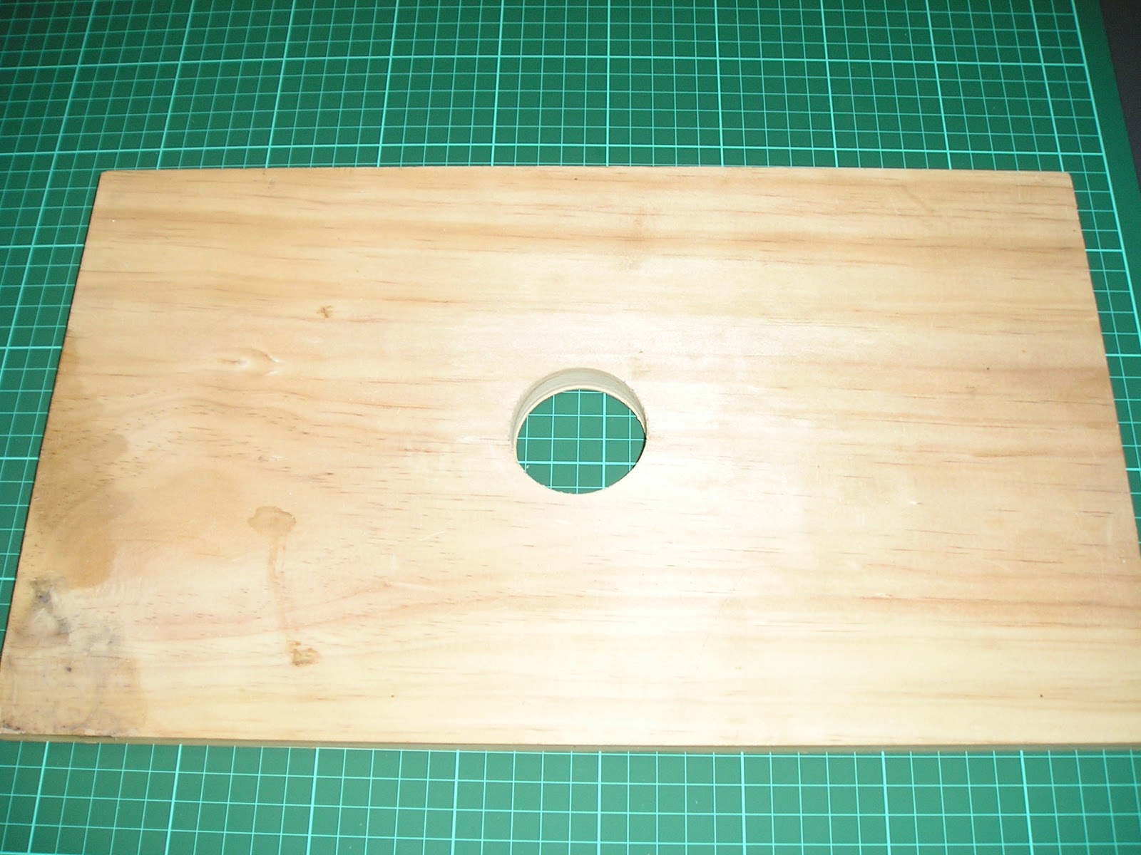 |
| Hole saw cut hole into a piece of timber to accommodate the bearing depth |
-

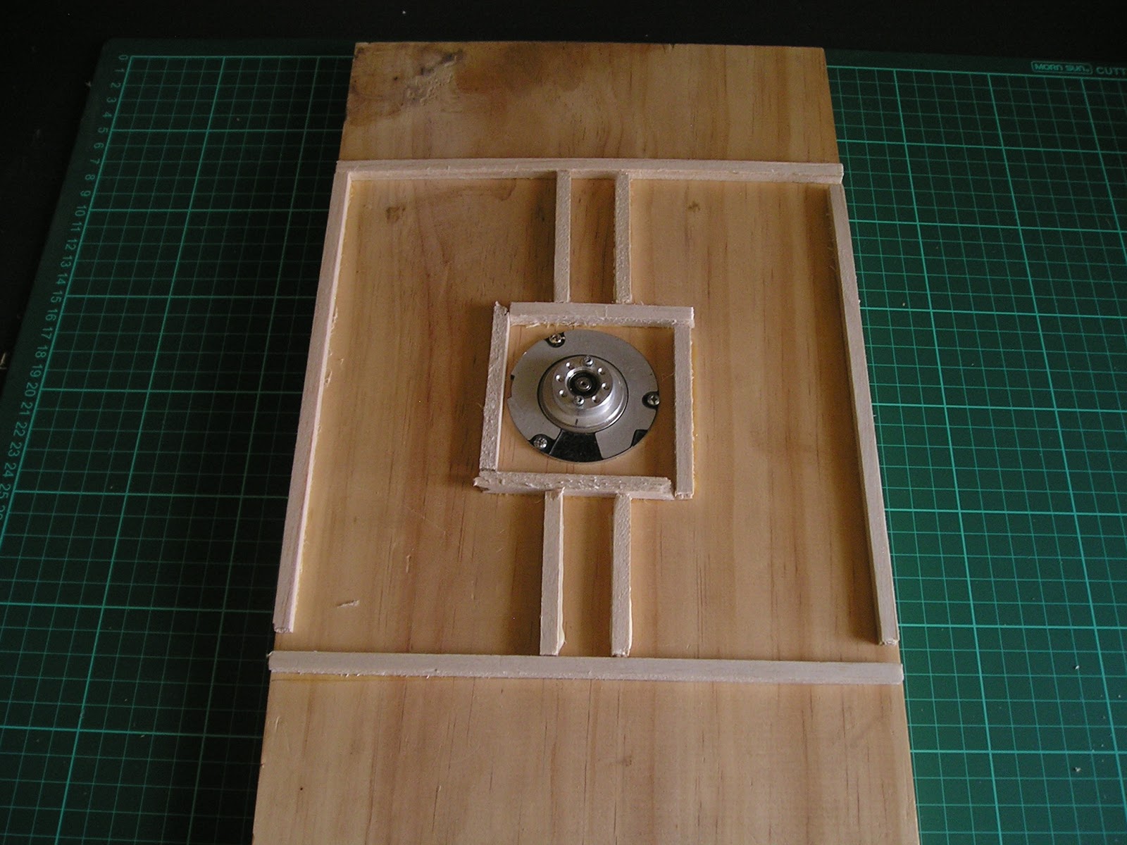
Bearing secured on timber with 3 screws
-

Brass turntable sides cut from scrap brass sheet, and assembled on a base of brass
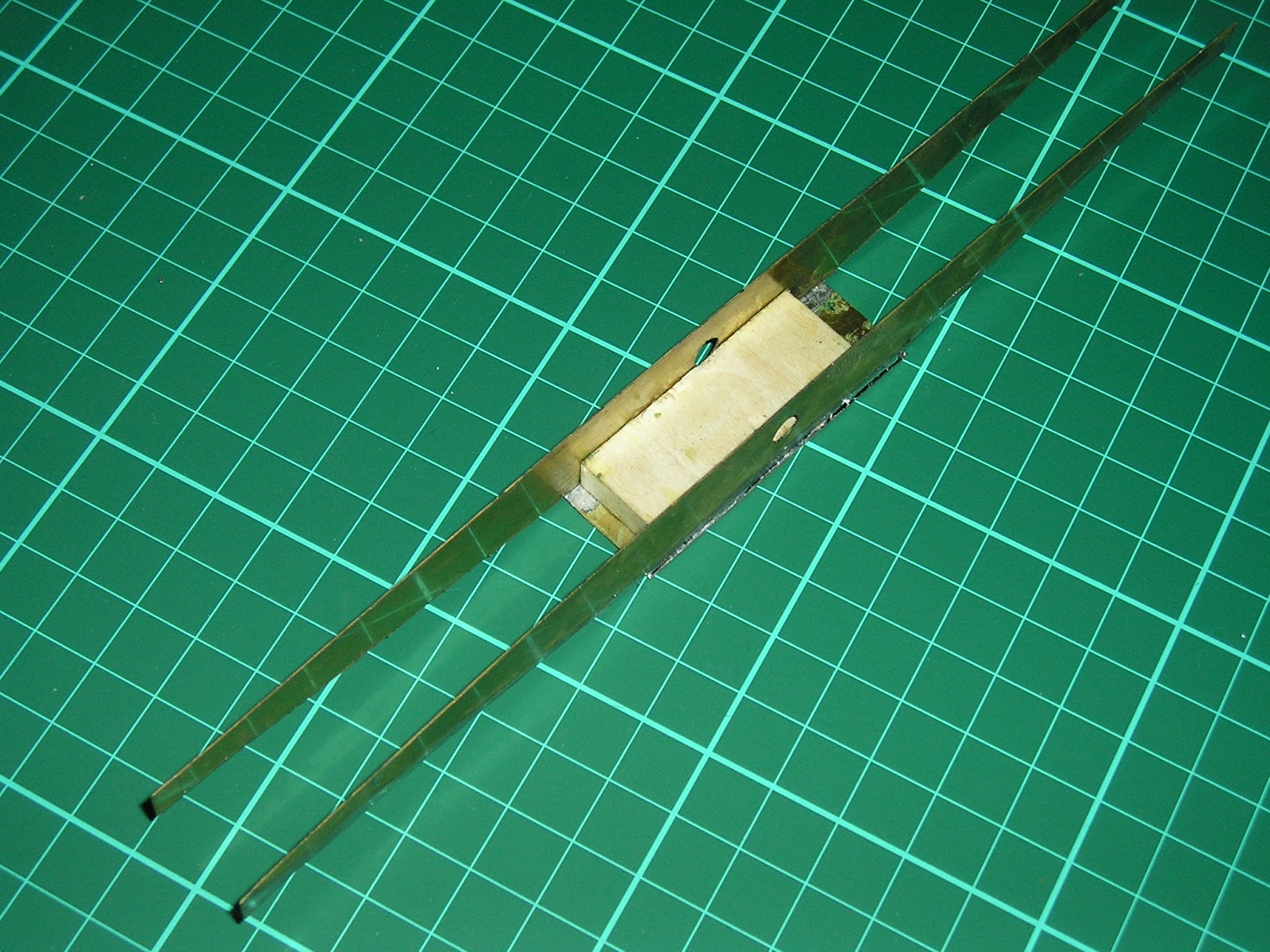
View from above. Note the wooden block used to space the sides, and also maintain the joints being square
-
-
Brass turntable assembled on board for testing.

 |
| After securing the base to the bearing with the two screws the height at each end of the turntable bridge was tested with a makeshift pile of boards. It is vitally important that these align. The harddrive bearing has ZERO slop. I have added one of the two angled bases so you can tell what end is what |
/

 |
| extra brass added for the walkway, and an upper support brace has been added |
-
- Bulking up turntable pit
 |
| Balsa framing |
 |
| Glue an MDF top with clamps. The top of the bearing pops through a hole in the MDF, and sits around 2mm higher. Check to ensure the bearing still freely rotates. The glue is intended to be permanent, so no more bearing adjustments are possible after this step |
 |
| Two 21cm (60 scale feet) of rail were cut, and assembled on PCB sleepers. Don't forget the electrical gap |
-
Ring and Abutments.
There are probably a lot of ways to
construct these, but I chose a method that works for me with the tools, and
material I had
 |
| I drew a circle using the end of the turntable as a guide, and then proceeded to glue on scrap blocks of balsa to act as the base for the future ring rail. The balsa thickness was chosen so as to allow an assembled ring rail to fit under each end of the turntable bridge with not much spare space. |
 |
| The gaps between the balsa blocks were filled with Aldi brand filler, and once dry, quickly sanded. Painted concrete, with a ring rail above, any imperfections will look natural. The bearing is only just visible, but looks OK. The pit will also need to be filled with a slope matching the bottom of the turntable bridge. Note the track now added to the top of the turntable - this is not yet secured. The abutment timberwork is also missing, but I do have the track baseboard extensions down. |
 |
| Detail from Cootamundra turntable. A sign like this would add some spice to the fascia on the layout |