Wednesday 27 December 2017

Murrumbidgee River Bridge - Part 3. 2nd span, and painting

Modelling can be very tedious at times.  Having finished the overhead beams on the first span, the second span was just a long slog on the workbench.  As I was now confident on my technique, the remaining girders were mass produced, and then fitted to the second truss span over a period of 3 weeks 


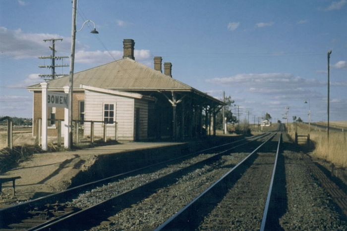
The Murrumbidgee River flooded last year - this is a picture taken of one of the billabongs during the flood, Note the gum trees, as this is some of the effect I hope to have around the bridge model.

Girders ready to be installed.  The above represents around 12 hours of workbench time

The instructions of the kit recommended dunking the completed bridge span into paint, and allowing it to drip dry,  Whilst  this had the advantage of speed, I have doubts over this method, as well as having sufficient quantity of paint.  In any case, the brass had to be cleaned of flux, fingerprints, cobwebs, and anything else that shouldn’t be there.

Rinsing under the tap was all I had done so far, but evidence of green verdigris in certain areas, showed that the tap  does not get rid of all the flux.    So the search started for a suitable container where I could scrub with a toothbrush, and use chemicals if needed.    Each of the spans is around 50cm in length.  To cut a long story short, (and no, the house bathtub is not suitable),  I made my own out of timber, and plastic film.  My inspiration is thanks to a display of R/C boats that I saw at the Newcastle model exhibition many years ago.  They had made a large shallow pond  on the floor of the exhibition hall using black plastic and bricks

The timber is scrap I happened to have lying around  

The plastic is double skinned to prevent leaks in case the upper plastic film is damaged.


Scrubbing was with cream cleanser, and toothbrush.  Followed by a rinse.  Then repeat.  Check for any verdigris, and if present, break out the ammonia and salt solution.  Wear gloves.  Rinse again.

After cleaning, the next stage was to attach the rivet shim to the upper, and lower chords of each span.  The shim needs to be carefully cut to size.  Checked for fit, I then glue the shim to the span.  Why glue?  Applying heat in the form of a soldering iron will cause the shim brass to expand, and then contract whilst it  cools.  I am not skilled enough to be able to control this, and any distortions in the rivet overlay will be difficult to correct.

Underside of the span, showing the rivet overlay.  Each of the main uprights are secured to the span with a pair of triangular gusset pieces made from scrap brass.

The glue I am using is 6 minute, 2 part epoxy from Great Planes in the USA.  Mix 2 parts equally, smear it over the bridge girder, and attach the rivet overlay.  Weight it down.  After about 10 minutes, remove the weights, and repeat on the next rivet section

Prior to painting brass, I like to provide a key for the paint with a light vinegar etch   The term used is “pickling”.  The vinegar is a mild acid, and the process gives a microscopic roughness that allows better adhesion of the paint.  My homebuilt container was half filled with fresh vinegar – about 1200ml.    As the bridge span is not covered by the vinegar, I am turning the model every 15 minutes to a new side.  You may notice a slight “pink” tinge on the brass after the pickling process, and this is a good sign.  After each side has been treated,   rinse the span and allow to dry

I am hoping that the vinegar treatment would allow me to skip the “self etch black” primer coat, and go straight to the final paint coats.  The self-etch black is not the easiest of paints to spray, and the bridge is rather a big model  The paint I am using is Floquil “Grimy Black”, thinned with turpentine, , and sprayed with a Badger 200 airbrush.   Pretty nasty stuff, so make sure that things are well ventilated.   Note. I know I should be using Xylene as the floquil thinner, but my experience with that product, besides expense, is that it dries far too flat. The turpentine , if anything, takes a bit longer to dry, and dries with a slight satin sheen.  And the other question is why Floquil?  Well, I have accumulated a supply of this excellent but now discontinued product, and to not use it would be rather sad, particularly as it sprays well onto brass, and gives a nice finish.

The main problem (other than the size of the span) with painting the bridge is the space between the 2 lattice etches on each side.  One had to try and avoid getting a shadow mask effect, so the airbrush angle of attack needs to be varied with each pass over the bridge.  My suggestion is that you do not attempt to complete the full span in one spray sitting – after you think you have painted the lattice, then allow the span to dry, and inspect for imperfections in a bright light.  Once you are happy with the lattice, then paint the remaining beams. 

One span painted.  I am happy with the colour, as it is close to the colour I remember on the real bridge.  The second span is still to get the pickling treatment, and then the paint. Note too, how the painted span only has 3 overhead support trusses. .  This is because the real bridge "shared" a support at the end of each span. .

 
The second  span should be a bit easier, as I had previously painted the insides of the lattice black (see part 1).  I will have to give the first painted span an additional coat, because, as expected in good light, there some areas where the brass colour  is showing through.  However, the effect of even this initial paint coat  is magic.  It is good to get a few wins on the way


The next part will be the wooden track support, and track.    

Until then, happy modelling

Saturday 9 December 2017

Murrumbidgee River bridge – part 2 – the overhead support beams

I am not sure when the Whitton truss bridge across the Murrumbidgee River at Wagga had its overhead arch girders replaced with steel beams, but it was before 1970.  And I do not know the reason, as the double track Whitton arch bridge at Albury over the Murray River still has its arches


Shortly after being built in 1879, this NSW Archives picture shows the Wagga Wagga bridge, and the timber trestle


In any case, I needed to model the Murrumbidgee bridge as it appeared in 1970, and that meant scratch building the overhead “U” support beams.   The first part of the Murrumbidgee bridge blog post is way back on the 26th June, 2017.  I finished that blog post saying that I was waiting for ABS styrene from China, or a source of brass “C” channel or the correct size.

The bridge as it appeared in my June 2017 blog. 


To cut a long story short, the styrene “C” channels from China were substandard, and I was unable to locate the correctly sized brass “C” channel.  However, I don’t like to leave projects sitting around for too long, and I wanted a distraction from the pain of shingles (yeah, that is another story), so a start was made. 
The styrene “C” channels, whilst poor, could be modified.  I cut out 7.5 cm sections that were more or less straight from the 50cm lengths supplied; and reduced the height down to approx 1.5mm.  These I put into a jig to hold them at the correct distance apart, whist I glued the styrene spacer plates on.  Unfortunately, removal of the jig stressed the joints out, and the whole lot disintegrated.  Better to find that out now, than after I had spent any more time on them.

The failed girder attempt with styrene


As no suitable brass “C’ channels were available. I had little choice than to fabricate my own from strip brass.  In this case I was very lucky.  I had in my supply of North Yard brass strip, enough 1.5 x 0.25 x 150mm, and 3.0 x 0.25 x 150mm strip pieces  to fabricate the 3.15 metres of the “C”  channels of the correct size for the bridge.  Yes, that is a lot of brass strip

Parts needed to make one 150mm strip.  This completed strip will be cut into two 7.5cm sections. This is a fortunate measurement, as it eliminates waste of the brass.

Once the “C Channels” were made, I fitted them into the distinctive “U” shape of the prototype, and matched a pair back to back, and soldered spacers to hold them a scale foot apart. 

Three 7.5cm sections make one half of the "U" beam


One completed "U" beam.  The spacer plates are 3mm strip brass.


  All these measurements have been guesstimated from the prototype photos I took during the bridge replacement over a decade ago

New concrete support piers were formed whilst the Whitton Truss bridge was still operational. The actual replacement of the bridge took around 3 days. The spans of the truss were cut into sections, and removed by crane. The old piers were then removed, and new concrete beams were laid onto the new concrete supports, and the track was then re-instated.

After being gas axed, the bridge truss sections were craned to one side awaiting removal. This view shows the interior construction of the girder quite well.

 
To match the prototype, I will have to fabricate 7 “U” beam supports, 4 on the first girder, and 3 on the second. 
 “U” beams were secured to the bridge using triangle gusset shapes.  These were made from sheet brass, but soldered to the bridge with 144 degree C solder, rather than the 60/40 solder I had used earlier.  I did this for 2 reasons – a)  I did not want to desolder the assembled “U” girder upright, and b) 144 degrree solder can flow with my small 25 watt iron on the large heatsink of brass that is the Whitton truss bridge side


The "U" beam fitted to the end of the bridge. The bottom had been secured to the bridge via a brass plate, although the triangle gusset plates on top are still to be fitted.  I was also concerned that I may have reduced the clearance too low, but I tested it with a USA outline diesel, and things should fit, provided I use lower profile sleepers.  But, I won't be able to run double-stacks through the bridge, 


One span, with two "U" beams fitted, and braced, and after removal of the temporary brace


The result was very strong, and I felt confident to remove the temporary brace, designed to stop the 2 bridge sides from collapsing inwards with handling.
I made a minor change to the assembly order of the subsequent “U” girders.  Basically, the 2 uprights were installed, soldered, and braced, before the overhead beam installed.  This was a lot simpler than my earlier method.

Detail soldering of one of the venter uprights


Angle braces were fabricated, and soldered to all 4 “U” beam assemblies.  These are purely cosmetic on my model.

I have been using fluxes to aid the soldering, and these need to be removed.  I have scrubbed the girder with kitchen cream cleanser, and washed the lot in water.  Further treatment will be needed prior to painting, but at least the model is no longer a clothing stain hazard. 

 
I have not yet finished the first girder.  The distinctive rivet overlay supplied in the kit will need to be cut to size, and glued [soldering heat would cause distortion of the thin rivet overlay]   to the flat brass on either side of the center uprights.  In some ways these uprights actually correct a problem in the kit, as the rivet overlay is around 6 mm too short to cover the area on the upper, and lower bridge chords where it was expected to go. I do not know if this was corrected with the newly re-released kit

As you can see, I still have to fit "U" girder supports to the second span.  Followed by painting, and then the sleepers and track can be added.  

This process is very time consuming.  I have not added up the hours I have spent – but my last “U” beam assembly took just over 5 hours to fabricate, and add.   I am sure that talented modellers might have used 3D printing to make the “U” beams - I am not in that category

Happy to report that after 3 weeks, the shingles pain has much reduced.  Whoever said Model Railways is therapeutic must have had me in mind.  I will continue with fitting the “U” beams, and with luck, will have painted the bridge for my next bridge blog post.

Happy modelling 

Thursday 23 November 2017

A Yard Crane for Tumbarumba


Way back in 1993, Stephen Johnson Models were offering a NSWGR 5 Ton yard crane kit for $55.  “Just what I need” when I bought the kit, although in 1993, I had little idea that it would take me another 24 years to actually build it.
Photo of the yard crane at Tarcutta (photo supplied by Pauil F)


The kit consists of 2 small etch brass frets, some lost wax castings, wire, rail, angle brass, 4 resin blocks, a set of instructions, and 3 resin jigs to assist in the construction.

  A review of the kit was in issue 179 (April 1993) of AMRM. (Thanks James).  This kit has a reputation of being difficult to build. The reputation is well earned.

As is my normal approach, I try and find as much information as possible.  Unfortunately, I had failed to photograph the full crane at Tumbarumba when I was there in 1980.  Greg Edwards Data sheets do have a HO diagram of the crane, but the details of the winch, and gearing was unclear. All is not lost.  These cranes can still be found in various locations, so  made a 55km trip out to Ganmain a few months ago, and photographed the 5 ton crane there.


Ganmain 5 ton Yard crane

After I started the build, Paul F sent me a good picture of the Tarcutta 5 ton crane pictured above.  As Tarcutta is on the Tumbarumba line, it might have been similar to the Tumbarumba crane. Disappointingly, the picture shows the “other” style of 5 ton crane used in NSWGR, which is a hint that the Tumbarumba Crane might also be this style, and not the kit version. But, these are the risks one takes.

Bob S (see the SCR blog link), also sent me some scanned  diagrams of the NSWGR crane from the railway archives.  These diagrams showed the winch and gearing in large scale.   These diagrams proved invaluable. Thanks Bob

Use of the jigs to build the “A” frames

Lower winch attached to one of the A frames

Anticipating a future step, I made winch spool rotatable.   However, I ran into a lot of problems in getting the top beams, and A frame assembled.  In retrospect, I should have made a jig to hold both A frames vertical, and not skewed.  Once the A frames are firmly held in correct alignment, then solder the pair of beams on top, and then add the cross bracing.  I won’t go into the method I used, but it almost resulted in the whole lot being launched into orbit
Even the bracket for the upper gearing was a significant exercise in alignment of the parts. 

Crane basically assembled.  Still have the set of steps to add to one of the A frame pillars, and the attachment of the ropes, and chains

Attaching the ropes, and chains was at best frustrating.  The instructions advise twisting the fine copper wire supplied together to simulate the chain.  This was straight forward, and from a distance, doesn’t look too bad.  Looking at Bob’s supplied plan, the upper chain goes from the trolley, and winds above the pulley, then go over the trolley to the other end, when it returns to the trolley.  (The instructions suggest the chain should go around the pulleys in the other direction, and the chain is hidden behind the top beams).  The chain descending to the bottom was also just a matter of getting the length right.  However, the brass wire supplied for the winch to the hook gave me lots of problems.  Basically the wire supplied was too hard, and fractured easily.   Solution straight forward.  I substituted some softer “tinned”copper  wire –taken from stripped insulated hookup wire.  This wire bent easily, and allowed me to wind it around the winch spool


Finished, painted with sellf-etch black, and weathered with my pastel rust powders.  Although the chains might have to be reworked if I find chains fine enough


Now that I have this crane built, I discover that there was also a crane at Ladysmith.  So unless another SJM kit appears, I might just have to throw money at the problem, and acquire the 5 ton crane model being sold by “The Model Railroad Craftsman” at Blacktown (even though this has an error in the bracket for the winch being on the inside of the “A frame”, and not the outside.  Who is going to be this nit picking?).  


Picture of the MRRC crane


Friday 10 November 2017

Bomen Station Building Plans

Over many decades, I have been acquiring information to aid my prototype modelling.  Unfortunately, the Bomen Station plans have not surfaced.   My understanding is that Bomen station building is unique in NSW, so it would be highly doubtful that a kit would ever be produced.  Drawing my own plans seemed the best way forward.


Bomen station was commissioned as an important station – being the temporary terminus of the Southern line in 1878, and the location of the town of North Wagga Wagga..  But soon after the station was built, the townsfolk drifted to South Wagga Wagga.   Bomen station remained as a staff exchange point, site of the Wagga meatworks, and for general goods.   I covered this in my earlier blog post
A trip to Bomen, armed with my digital camera was the first step.  After taking 50 or so pictures, I returned home, and printed 10.  Armed with these pictures, pen, and tape measure, I returned to Bomen and recorded these measurements on my pictures.  I used metric measurements, as this makes the reduction simple on a drawing


In 1974, I did Tech Drawing at high school, and I found these skills useful.  Whilst I probably should be using CAD, I spend too much time on the computer now, so it was good to get out my set squares, rulers, pencil, eraser, and paper, find a sunny spot, and do some drawings.  Before I started, I added up all the measurements, and compared the 2 sides, and the front and back.  I was out by 1cm on the sides, and 6cm on the front, and rear measurements.  This is well under 1% error, and reassured me that I had not made any major measurement errors.   It took around 6 hours, spent over 2 weeks to finish the plans. 


As I drew them to scale 1:100, a trip to Junee Library, to use their enlarging photocopier made short work of the conversion to 1:87.  My plans will not win any awards, but are suitable for marking out the sides, front and back on styrene brick sheet.  The one aspect that I know is wrong, is the roof. I initially thought a 30 degree slope was close, but the 25 degree for the end drawings is closer again.  I also have the chimneys in slightly the wrong spot – so I will have to go back to Bomen, and really look

What struck me is how big the station will be.  The HO scale footprint of the main building is 30cm x 13cm, and this is not including the Toilet block, and signal box (or indeed the car park at the rear).    I should be able to construct the station full size, however, I will do some more detailed track planning of the Bomen area to confirm I can fit everything in without the baseboards being too wide.
Now comes the “fun” part – actually building the station.

Happy Modelling.

Saturday 28 October 2017

Bomen - The original North Wagga Wagga


 Bomen is located on the northern side of the Murrumbidgee River bridge, and viaduct.  It actually predates Wagga, as the main line opened in September 1878.  In fact, Bomen was originally known as “North Wagga Wagga” when it opened.  As befitting a terminus station, a 2 track engine shed, inspection pit, and engine facilities were established, along with a fine station building.  A new town also sprung up – it is said that there were over 16 hotels.
The river bridge was completed in 1879, and trains were able to run to “South Wagga Wagga”, and later to Albury.  The engine facilities were relocated.   The name “Bomen” was adopted in 1882.  The  town that had come about due to the end of the railway line faded away, as almost everyone moved south to Wagga Wagga.
Bomen station survived as a crossing loop/staff exchange, loading ramp, and  a large abattoir.  Wagga City council was keen to grow Bomen as an industrial estate in the 1970s.


A rough timeline.
1952 signal diagram shows the abattoir, including sidings for stock unloading
1975.  Weekly notices have the establishment of a cannery (now run by Heinz), with a siding off the abattoir siding.  Freight rates for shunting this siding are $2 a wagon
1975. Weekly notices also mention a siding to “Hollanders”, which I understand was a leather tanning operation. Freight rates for this siding were $2.50 a wagon.  (The Hollanders siding attaches to the goods siding from behind the station building)
1979.  Saleyards closed in Wagga, and moved to Bomen.  A long siding was established off the “Hollanders” siding

1983.  Fuel depot created (as fuel depots in Wagga were closed), and pointwork also off the “Hollanders” siding

[Sidings at rear of station building - Left to right beyond the level crossing - , Hollanders, Caltex, Stockyards, and Austrak]

[Shunting the Abattoir siding in the 1980s.  Note the cannery siding just visible lower RHS ]
[Stockyard sidings were used for headshunts, and equipment storage]

[Shunting of the oil wagons onto the stockyard siding]

[Hollanders Siding was reasonably lengthy, and had its own right of way through the Bomen estate]

[Hollanders Siding crosses Lewington Street, and ends up at a concrete block loading dock.  The tin shed that was once there has long gone]
 [Rail approach into Heinz Cannery. Inside the building, the track still exists]

[The Bomen Abattoir has erased the track approach but the loading dock is still intact


As an operational layout, I am going to try and incorporate as much shunting interest as possible.  And this does mean that I will be stretching the 1970 timeframe a little.  Both the Cannery, and the Tanning facility will get modelled.  The stockyards, and fuel depot however, are essentially just relocated from Wagga, so I see no advantage in moving them to Bomen.  The other constraint is space;  I estimate I have around 4 linear metres for Bomen, and at most 600mm wide. 
-----------------

By 2017, Bomen has grown considerably.  The platform signal box, mechanical signals and staff exchange platform disappeared in 1983 with the introduction of CTC.  A small intermodal facility has been set up in the yard in the 1990s, Austrak created a concrete sleeper fabrication facility a short time later.  Unfortunately, both the abattoir and cannery have lost their rail sidings.  “Hollanders” relocated within Bomen, although the long siding and loading dock they used was abandoned.  The saleyards sidings saw their last stock trains by 1989, however, the sidings were retained for rail storage, and headshunt purposes.  The crossing loop was extended about 5km towards Shepherds Siding.  As oil trains stopped in NSW around 2007, the oil depot saw no rail activity until last year, when all the wagons were recovered.  The oil sidings and stock sidings were pulled up, and new roadworks for the future Genesee and Wyoming intermodal were created.  And in October 2017, the old pointwork on the Austrak siding was removed, and new concrete sleepers  laid.   The Bomen station and platform remains, heritage listed, although it is unmanned.  The Station masters cottage is still standing, it too  no longer occupied.   The gatekeeper cottage/gatehouse is long gone, and interestingly, the automatic level crossing lights and bells that replaced it are themselves out of use due to the aforementioned intermodal roadworks

[ The trackwork as it exists today.  This track was only installed last week (October 2017)( The Caltex oil depot is still visible in the background, but all pointwork has been removed.  The siding now serves just one customer - Austrak.  The original road at the back of the station, has been reworked onto the old stockyard siding alignment - part of the new intermodal yard - 
[Austrak - the siding is to the LHS of the picture]


I want to thank all the people who have supplied me with photos, particularly Rod S, and the Wagga Rail Heritage group, and Pete N for access to records.  A number of  pictures too by the late Andy Browne have added greatly to my appreciation of Bomen