Showing posts with label Signal box. Show all posts

Saturday, 5 November 2022

Bomen Signal box interlocking


Bomen Signal box Interlocking - or - who is going cranky

When I was designing the future Wagga layout, I had anticipated incorporating my partially built 56 lever frame only for the Wagga station.  The station at Bomen though didn’t seem that important in the scheme of things, and I was not going to worry about this until the layout was constructed.

As it turns out, I have not as-yet been successful in finding a builder, who is willing to undertake construction of my train room.  So, projects that were on the back burner have advanced instead.

My picture of Bomen was after the signal box removal in 1983


Prototype Bomen

Bomen was a crossing loop, with some additional sidings.  Only the sidings for the meatworks stock yards were interlocked by the frame, the long siding into the meatworks, the siding into the canning factory, and the one for the leather works were on a simple ground throwover levers on the yard tracks 

Bomen’s signalbox according to Bob Taafe’s signalbox book, was relocated from Uranquinty around 1941.  It was situated on the southern side of the station.  The frame was 20 levers.

A picture from the internet - showing the signal box

After I had enlarged a small pixel image of the signal diagram which was used for the interlocking diagram, a far better resoluton image showed up.  Careful checking found an error - lever 10 was actually a catchpoint with signal attached, where Bomen frame as modelled, as this lever as a signal, with a catchpoint attached.  Shouldn't affect operation


Modelling.

Way back in 1982/3, the British magazine “Model Railway Constructor” ran a comprehensive monthly series authored by Martin Goodall, on constructing a layout based on the GWR station of Bodmin.   Parts 15 through 23 concentrated on signals, and interlocking.  Inspirational, as well as informative.  The parts dealing with mechanical interlocking were the best I have ever seen on the subject, and from the time I read the article,  I took an intense interest in this obscure aspect of modelling.

(copies of the articles are at the end of this blogpost)

Unfortunately, this interest started just after the NSW railways removed the signalboxes at Wagga, and Bomen in 1983. 

But, luck was on my side.  A fellow modeller, who had also seen the MRC articles, had actually started making interlocking machines in approx. 1/10 scale, using the principles of the MRC articles.  Then around 1990, the Defence department moved him to Queanbeyan, where I was living, and I got to know Tony.  Tony Kociuba’s layout Manuka, was featured in AMRM way back in issue 188 (October 1994).   I got to work a fully interlocked lever frame at his home, and at exhibitions.  After a while, Tony trusted me to build a large lever frame under instruction and guidance, that being the 56 lever frame of Wagga Wagga .

The Wagga signalbox frame was built by me in the 1990s - still needing to be interlocked.


Since moving to Junee, Tony and myself have maintained a sporadic contact.  When Tony found out about my plans for the layout, he volunteered to construct Bomen’s frame as a contract build for his Mackenzie in HOLland hobby business.  I supplied Tony with as much information I had at the time  unfortunately, with the lousy small pixel signal diagram picture.  It was also a bit of a fiddle, as my rendition of Bomen’s track plan is mirror image of the original.    Tony now lives in Bendigo, and detoured into NSW via Junee to show me progress, and later the finished lever frame – fully interlocked.


Tony made 2 visits - the first one showed me the progress of the frame, prior to interlocking


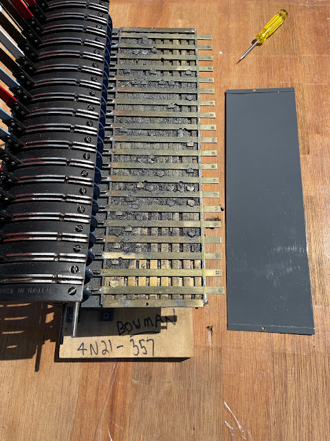
On the second visit, the frame had been finished.  Here is the interlocking with the cover removed.  Note that all the tappets have numbers, which helps if the frame ever gets disassembled . Tony adds a lot of graphite for lubrication 


Now I have to learn the frame, and crunch the levers in the correct order to free up the mechanism   Excess force will break something, so you don't want to pull the levers in the incorrect order.  It will be a challenge for the future Bomen operator too, but learning the frame was part of the real signalman's job - and simulating this on a model takes things to another level of realism

.

Albury to Junee.  The levers have to be pulled in the pull chart order as seen on the signal box diagram.  

Albury to Platform road

Junee to Albury


Integration into the layout will be via electrical connections, rather than through a mechanical links direct off the levers

Signals will of course have to be built.


Trouble cat - gives an idea of how big the lever frame is.  She may not yet be the station cat, but takes a lot of interest in what I am doing


Observation.  A lot of older magazines contain a wealth of information.  Some of these publications get converted to a digital format, but a few never do.  It saddens me to see the wisdom of these now forgotten publications, consigned to landfill, or recycling.  Please, consider the process that brought the articles contained within to print.  The author, the editor and their desire to not only sell magazines, but the sharing of knowledge.  We are all better modellers by learning from their experience


Sunday, 10 May 2020

Future Proofing


Future Proofing

Last weekend, Rod sent me a great picture of Wagga signal box, and the cottages beyond.  Rod knew that I was looking at modelling the cottages, and this was the first picture I had showing the roof pitch from side-on.  I was also excited, as the signalbox was painted in the colours I chose for my HO model, AND the heater had not been converted to gas.  
I dutifully saved the picture in my folders showing Wagga’s railway infrastructure.
<picture from Rod>


Picture of the Wagga Wagga Signal Box, date 1978.  Photographer Ken Lewis

On Monday, I powered on the laptop, and I had a totally blank screen.

My Acer Aspire 5542 laptop was probably at the end of its life, having bought it in January 2010, with the then new Windows 7 operating system.  In the intervening years, the only hardware problems it had was a dead CMOS battery in 2016, which also resulted in a dead screen.  So thinking that maybe the CMOS battery had again failed, I totally disassembled the laptop to gain access to the motherboard hidden within.  Unfortunately, the new CMOS battery failed to bring the screen back to life.
The only quick way forward was to acquire a new laptop.

Rebuilding the new laptop has been an adventure, and has made me think about the risks one has in technology, and how that could affect our model train hobby.

Backups. 
Fortunately, I had a recent backup of all my data files dated April 30, and whilst Rod’s supplied picture was not on the backup, I had not deleted his earlier email.   Some people have suggested that I store all my data in the “cloud” and allow another company to manage it.  This has the advantage of not worrying about backups, and being able to access the data/images on any PC or smart phone also connected to the cloud.  Let us hope the cloud continues to operate, the internet stays running, as you have no control if they don’t.

Things outside your control
Those who saw the “oval” pictures on my two more recent Blog posts from March,  will see that certain unexpected changes happen. I still do not know what caused the issue, although Google did say they were working on the problem, which affected quite a number of blogs.  Now it was “fixed” but there was no automatic restoration of my images.  This was a manual process for me. Fortunately, I had my original images

Software and Hardware compatibility. 
Over the years (I started my computing degree in 1978, and was very familiar with programs coded on punch cards), and many "dead" programming languages (like Cobol - although I hear that there are still active Cobol programs out there).  But, a lot of my electronic stored data,  has been lost in the intervening years, as well as the software to read the 5.25”, and 3.5” floppy disks have also become scarce.  This might be considered progress, as we moved onto CDs, USB Thumb drives, SD Cards, DVDs, high capacity Hard drives, and now solid state drives.  Each move forward has left some of the old hardware behind.  I wonder how many people had libraries of Beta, and VHS video tape (many containing Railway videos) that they cannot now view?

Companies going out of business.
 During the reconstruction of the files, I found that the company that supplied my Solar monitoring hardware, had gone out of business.  Finding the drivers, and software to reconnect my hardware was non trivial.  This leads to another  aspect that also affects the railway modeller.
In the last few years, we have had the retirement of the owners of the following companies (there are more)  Shinohara, Mashima, Grandt Line, PSC, NWSL.  Luckily, some of the product ranges have alternatives, or have been retained, either with a new owner, or by acquisition by another company.  Things we are so comfortable with, can suddenly change.   Anyone with Virgin Velocity points will know how quickly things can change in just a day.

But who is to say, our carefully selected train control systems, signalling, etc systems that we buy for the layout will be available if the company that makes them goes broke?  You can hope that by adoption of a common standard, such as DCC, and JMRI, will future proof things somewhat, although, if your layout was controlled by my laptop that just died, you are instantly out of the model train operation business until you can find a replacement, and reload all the software.

And do you have the expertise to diagnose, or repair what has been installed?  Reliance on a few talented  individuals for all the electronics black magic is also a recipe for disappointment when failures occur.  Overly complicating things, and almost full automation is probably not a suitable way to proceed with a layout, unless you are into such things. 

What can you do? 

Sure, keeping a supply of spares is mandatory, and I have duplicates of the NCE Power Cabs, CDUs, power supplies.  I would also suggest that you should test them every so often. 

We take everything for granted at our peril.

---------
An update.  My "new" laptop failed last Thurs, and is back with the retailer for repair, replacement, or refund.  After spending a lot of time on preparing this blogpost on the "new" laptop, I have had to do it again on a borrowed computer  Fortunately, this was the only document affected, and I still have my 30 April backup.

Wednesday, 28 August 2019

Wagga Wagga Signal box - details


Wagga Wagga Signal Box – details
Interior detailing is not something I have concentrated on in the past.    I had limited my efforts to models that could be seen, but in reality, I was more interested in the next project.


Automatic Staff exchange at Bomen.  A 44 class has just exchanged staffs on the "pop up" staff exchanger instrument in 1972.  Thanks to Peter Neve for supplying this great picture

But, it was time I challenged myself.  Over the years,  I have seen either first hand, or in pictures, some outstanding structure modelling.  The first was at the Pendon Museum in England – which I visited in 1985.  The models were modelled after real buildings, and the attention to detail absolutely amazing.  I now own many books on the modelling techniques used at Pendon, and these still inspire. 
More recently, with the introduction of 3D modelling via CAD, many detail possibilities are becoming reality.  One on the best modellers has been Jack Burgess, on his Yosemite Valley Railroad HO layout.  Jack’s structures were based on the real VYRR, involving much research.  Jack became very accomplished with styrene fabrication, but his modelling of interiors has bordered on the extreme – for instance, turning a HO scale Coke bottle, and half eaten sandwich on a desk.  His station at Merced has a full interior – and to get around the interior being invisible from the outside, Jack has installed a periscope which views the highly detailed interior, and any trains that happen to be passing outside the station window.  He now uses a lot of CAD in his modelling – and his view on 3D printing is that Shapeways have spent $100,000 on a 3D printer, why compromise with a hobby version.
Locally, it is hard to ignore Ross Balderson’s modelling efforts.  His Sydney Station, and Elizabeth Street N scale layout (featured in AMRM issue 288) was museum standard – and his current project of Newcastle takes that modelling standard to the next level.

My modelling has a long way to go to reach these lofty heights.  But, one has to start somewhere, and skills learnt, will hopefully make future projects easier – even if it is “what not to do”

My last blog post on the Wagga Wagga Signal box showed the levers, and the block shelf.  But I knew there were more parts to install.  The disappointment with the UK signal box interior, meant a lot had to be scratch built

I thought I would start with the desk - my Cooma signal box interior picture showed a roll-top desk, which seemed an easy one to start with.

I got the desk sizing by checking with a Carters Australian Antique guidebook that I happened to have.  This is not quite the Cooma style, but it was only the dimensions I was after


What 27 pieces of styrene, and a spare hour  can make.  The 10c coin is almost the same size as a US quarter for anyone not familiar with  Aussie currency
I also made a swivel chair, sized on my chair in the modelling room. It was only after showing it to others, was I informed that in 1970, swivel chairs would have 4 leg supports, and not the 5 that I have modeled. One is always learning  


One of the important items was the staff instruments.  But what style were they?  I didn’t have a definitive picture of the instrument in the signal box, but I suspected miniature.  I confirmed this after reading a passage in the book “Safe Signals” which stated that all the token staffs on the Junee-Albury section were replaced with miniature staffs in 1931.  Did anyone make a miniature staff instrument in HO?  Model Engineering Works does make a resin model of a large staff machine, and a purchase would have saved a lot of time.  But, I thought I would see if I could fabricate one.  My result is pictured.  The size was slightly larger than HO, but it was based on the thickness of the 10 thou styrene, and proportioned accordingly.

Scratchbuilt staff instrument, on a plinth.  The clock was one of the few parts I was able to used from the UK signal box interior kit that I had.  Very similar in style to a Seth Thomas clock, used widely on the railways.  The clock face,  hands and numbers are all pencil scratches. Don't look too closely 


The pot belly stove was another  part from the UK signal box interior kit that I could use.  Like the staff instruments, it is over scale for HO.  Was this the design used in NSW signal boxes?  Probably not, but until I have a picture, it will do.  A bucket is used to fuel the pot belly stove – which I turned to a conical shape from a large styrene sprue, painted, and filled with “coal”.  

I made 3 of those staff instruments - two for the main line north and south, and the third for the branchline out to Ladysmith.  I was advised by an ex railway signalman that the staff instruiments were most likely near the door, but their siting is a guess. Same with the desk and swivel chair.  I have put these on blu-tac in case I have to relocate them.  The pot belly stove, and bucket of coal are approximately in their final positions.
 The door for the signal box was missing.  Both Wagga, and Bomen had a window in the door, but Greg Edward’s data sheet signal box diagrams only showed a solid door.  I found a prototype window door at Stockingbingal a few weeks ago.  To make it, I tried a different technique.  I cut out a block of DVD plastic to the size of the door, and used a bow pen to draw the mullions to the window.  Then added the styrene strip to the outsides, and painted over the door.  Results are encouraging – and the painted mullions are a lot finer than the styrene ones I made for the windows.  I may have to revisit the signal box windows at some stage.

Stockinbingal in August 2019.  The station had been "restored" to a heritage scheme, although now sadly neglected.  The original signal box though had a sign saying that the signalbox was still operational.  With the alignment of the new inland rail coming through Stockinbingal in the future, who knows what is in store for this station

A railway padlock now secures the Stockinbingal signal box door

My Wagga Wagga signal box door.  I even fitted a door handle - actually the head of a pin.


Each staff instrument needs an external bell to inform the signal man of changes.  I have fitted a block shelf with 3 shelf bells on the wall behind the staff instruments

Clock, bells, stovepipe extension, and door added to the wall.


2 more block shelf instruments, and a station diagram added to the rear wall.  I am not convinced on the size of the diagram, but it does seem to fit the size of the pictures I have of the real diagram


On the outside of the signal box, I fabricated a stove pipe for the roof.  A “WAGGA WAGGA SIGNAL BOX” sign printed on paper, adhered to styrene, and dull coated to remove the paper look.  To finish, some powder weathering on the roof, and on the clapboard

Still missing is the porch light, and of course the signalman.  Something for the future when I rediscover the microLED lights I purchased last year

Stovepipe made from 2 styrene rod shapes.  The weathering on the roof, and clapboards doesn't show up that well in the direct sunlight
View of signal box from the Albury end


An old adage in modelling.  If you model something badly, it is worse than not modelling it at all.  The eye will quickly pick up an error, where an absence is not readily noticed.

Time to move onto something else.


I will leave you with some signal boxes pictures on the south that may be of interest.

Happy modelling.


Harden South in 2013.  The signals are no longer controlled through this box.  The "Bushells Tea" sign on the building in the background was also spied and later photographed   - never let a chance go by.
Interior of Harden South, photographed through the window on the door.  Most of the parts that can be removed have been.  Even this abandoned view can give clues on what was here.  The cupboard on the far wall is something I haven't modelled for Wagga, and maybe need to.  The colour scheme for the walls.  In time, images like this could be valuable for historians. I understand that the stairs leading up to this box have now been removed. 


Travelling to Stockingbingal, I stopped at Cootamundra West.  The signal box is on the platform.    Again, abandoned, with  asbestos issues, although I noted a newish looking Fujitsu split air conditioning unit installed   The telegraph pole looks like it was not rationalised before being abandoned

Inside of the West Cootamundra Signal Box.  Picture taken through a broken wall fitting.  Not much left

The telegraph pole next to the one on the Cootmundra west platform is being covered by a tree, but again, great details exist for modelling


Wednesday, 24 July 2019

Signal Box construction - adding details

Signal Box construction - adding details

Hot on the heals of Pete Neve's staff exchange picture (last blog), Bob Taaffe sent me an internal image of the Wagga Signal Box.


Bob Taaffe photo of Wagga Signal Box in 1975.  All levers are shown, along with the signal diagram, block shelf, and some additional details on the rear wall.  If this is the standard of the photos in Bob's forthcoming books on NSW signal boxes, we are in for a treat.  (Picture used with permission)

Downpipes
Previously, I have struggled with fabricating downpipes - trying to bend metal to shape was always a hit-n-miss operation - and often the gluing of them left a lot be be desired.  However, I have come up with an alternate method, which I am sure has been used by modellers  previously, but I have never seen it written about

Start with a 0.040 styrene rod.  This size is slightly smaller than 4" diameter, and not a bad compromise with prototype fidelity, and structural strength in HO scale.  
Cut the rod at approximately 45 degrees, and position (as shown), prior to glueing with MEK.  I use a glass plate over the "cutting mat", which is not affected by the glue.  This keeps the downpipe "flat" whilst the glue dries
Add the pipe to the model - I used MEK glue to attach the pipe, as I hadn't painted the walls.  Note, this pipe should extend lower to ground level, but this would have been impractical at this stage.  The omission will be addressed once I have completed the base.
Bomen box also got its downpipe.  Rather spoils the clean lines, but it was on the prototype
Some hand painting done on the base, again to match the colour of the prototype.  Will need to be redone.  Some green/grey door trim also added.   The entire box (less the windows) was then dull coated.  This kills off the shine of the styrene, as well as giving it a painted feel - a bit of a fudge to save time - only possible as Wagga's box was white.   Note that the roof of the signal box now has guttering, and fascias.

The stove pipe on the roof (and pigeon poop, and weathering) is about the only thing remaining to be added to the roof

The dull uninteresting side?  Without any prototype pictures, I really do not know what details I am missing.  Maybe telegraph lines, vents.   As it is also the side that won't be seen on the layout, I won't stress.

Signal box levers
As I mentioned before, the Uneek levers from Anton's trains were modified, and a new signal lever baseplate made, as the Uneek ones has inadequate spacing.  Wagga had a 56 lever frame, but only 41 active levers, and 2 unused ones by 1970

Using Bob Taaffe's picture, I have attached all the levers to my frame matching the lever positions shown.  
Painting took a long time, and very fiddly.  Yes, the lever colours are correct.  In retrospect, I should have painted each lever separately, and repositioned the painted lever to the frame one by one.  After all, I had attached a pin to the base of the lever, and drilled holes, which would have made things a lot easier.  Keen viewers will also sight the block shelf, and a block instrument  
A rear view shows that I have 6 instruments installed.  The block instrument in my collection has a dimension approx 5"x5"x10".  I have matched that with a 0.060 thou square styrene strip, painted gloss red, and after drying, cut to 3mm in height.  A extra detail was carving out the dial out of the red with a slightly dull exacto knife.  Not hard, just fiddly.  There possibly needs to be a few more block instruments added to the shelf on the Albury side 
More space in the signal box means more detailing.  I have a pot-belly stove, but the desk, chair, staff instruments, cabinets are all awaiting to be fabricated.  How are these are positioned in the box?  I am hoping that the pictures in Bob Taaffe's new book will give me an answer

Detailing to this degree may not be for everyone, but is ultimately quite satisfying.
--------------------------------
A late note:
I am planning to head to the Malkara exhibition on the 4th August 2019 (sunday), and assisting Al Harris run his American switching layout.  If you happen to attend, please drop by and say hello.