Sunday, 27 May 2018

Bomen Station –construction part 2


S65 passes Bomen in the 1980s

The next stage in the construction was to dress the windows and doorways.  Resist the temptation to assemble, until this has occurred.    As my windows and doors are not available commercially, the following pictures show the process.

Ladies platform side doorway on south eastern side. As cut out

Archway filed into the doorway.  I used a half round bastard file

Brickwork carved away above the door with a chisel knife blade. Be very careful with this step

New brickwork pattern scribed into the corbels.  I know this new brickwork should be flush with the surrounding brickwork, but it is extremely hard to tell

Some styrene strips added to "bulk out" the brickwork, as the slaters brick sheet is quite thin.  The one at the top was filed to the same arch shape as the brickwork.  The  thickened brick edges were painted to add depth

More styrene added, to form the woodwork.  The woodwork for the crownlights was cut to size from 20 x 30 thou. strip

One down – 18 to go.......

I used evergreen styrene for all the framing.  A month ago, I purchased almost every size of  evergreen styrene strip from “The Railcar”, and having the exact sizes on hand makes the work go quickly. Whilst it is possible to hand cut sizes from larger sheets, life is too short. 
Now came the fun part – assembly, where good preparation pays off.   The base of the station was cut from a 40 thou thick  sheet, and the walls added slowly, checking with squares.  Reinforcing with 80 thou size square strip on the corners.  The station also slopes away at the rear, so I had to bolster the front platform with yet more styrene strips.  Virtually no gap in the side joins, which only needed a quick light sanding to finish.

All 8 wall sections, and the base, prior to assembly

Back of the station after assembly.  Note the way the brickwork extends below the station base

Front of the station.  The extended station base is to accomodate the platform roof posts. Unlike most of the NSW stations, the roof extends over to the platform, rather than finishes at the station wall, with a separate awning to keep the sun and rain off the passengers.    I am also toying with the idea of an interior, although getting information, and pictures is not an easy task. If anyone has any pictures, I would be grateful to know of them


Brick painting
I tried a new technique (for me) in getting the brick colour.  I headed off to the Wagga Wagga  Bunnings store, and found a colour card that I thought was  really close to the brick colour at Bomen station.   Then I asked if a 250ml sample pot be made for me.  The colour selected was Taubmans “Rusty Rail” – which seems quite appropriate for a railway station.
Back home, I mixed up a 10ml with some thinner (I had run out of Tamiya thinner, so used Simply Glues Y6b thinner instead), and sprayed using a badger 200 airbrush.  I was very pleased that the paint sprayed nicely.    At around $6.00 for 250ml of paint – a BARGAIN for a hobby task.  I hope the paint will stay viable for a while yet – the Bomen station lamp room/gentlemans toilet is a future build.
What did surprise me is how close the Slaters brickwork colour was to the “Rusty Rails” colour.  Under artificial light the slaters brick looked too pink, and even Rusty Rails, which looked right at Bunnings, is a bit bright compared to pictures showing the whole station.  Conclusion - Colours are fairly subjective on a model, so don’t get too hung up about it.

After letting the paint “set” for 24 hours, I got out my small paint brush, and carefully repainted all the trimming in Floquil Antique white – which is a good match for the off-white colour of the station.  This is one of the drawbacks of attaching all your windows and doors prior to the painting – although I am not sure I could have done it any other way, as there is unfortunately a bit of variation in my handcut door and window openings.   
Not quite finished the base yet. The lower concrete “barge board”, and window sills are to be applied;  then add the mortar lines, and the windows and doors.   

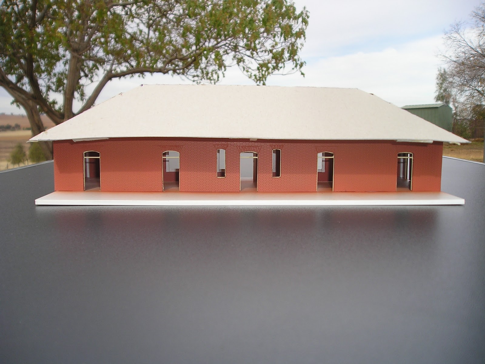
rear of station, with cardboard mockup roof.  

Station front - again with cardboard roof.  I might have to change my viewing perspective to see if the roof line matches the picture below

The real Bomen station - hopefully my model will look close to this when finished

Before stating on the posts, awnings, and roof, I thought I would check out the cardboard roof made earlier, on my station.  This is the last time for any changes before starting to cut out more styrene.
In the meantime, I am trying to get some details on the station interior.  Having an open door, and people will add some life to the station when completed.   I have also made a start on the awning supports posts, but you will all have to wait a little longer for this bit.

Happy modelling

Monday, 21 May 2018

Bomen Station –construction part 1


The Bomen station was originally built by Charles Hardy of Wagga, as part of the establishment of the terminus of the Main south line into North Wagga Wagga.  Charles was the owner of a steam powered brickworks in Wagga Wagga, and he also built the Station masters residence, the engine-shed, and other infrastructure.


S66 passes Bomen in June 1980.  44209 with a RUB set. Note the staff exchange stand, and hoop

Station front a few years ago.

Station rear


According to notes I found at the Junee Roundhouse museum, the plans Charles used were his own
This is a round-a-bout way of saying that it was unlikely that a model kit would ever be offered of this station. 

After I drew up the Bomen Station plans, I worked on other projects whilst sourcing the styrene parts I would need. 

Front and back views, with an marginally incorrect pitch on the roof.  I drew the plans to 1:100, and then enlarged them to 1:87 on a photocopier.

End views shows the fall of the ground away from the platform level. This fact has meant that my walls will have to extend below the platform, which slightly complicates the model build 


The first step was to make up a mockup out of cardboard.  This was mainly to test the roof profile, as my plans were not as accurate as they should have been.  Making a cardboard building is a useful exercise, for it also gets me thinking about the project, and tests out a possible construction sequence.   A better grade of cardboard would have been better than the cereal packet card I used,  and perhaps glueing on a copy of my plans front and side elevations would have given a nicer visual result

Cardboard mockup, showing the rear of the station building.  Took about an hour to construct.  Making a mockup is a fast and cheap way to populate your layout with structures, before replacing them with something better when time permits


The brickwork I found is not that close to the modified English bond that is on the prototype.  The brick styrene used is flemish bond, a sheet from the Slaters range.   Whilst this is a British company, and one would expect the brickwork to be OO scale and large for HO, in reality, the brick size was actually about right for the HO scale Bomen station.  But, all jokes aside, it should work OK, as only the best nit picker will know......

SE corner of the station, showing the english bond brickwork

Cutting out the windows and doors is a task that took me over 2 weeks, whilst other priorities took hold.  I have kept the cutouts for possible use for the chimneys.  I have only one sheet of the slaters brickwork, and the Bomen station toilet and lamp room building is another that has to be made, so being frugal with the material is important. 
The wall edges were then sanded to a 45 degree angle, which should minimise the gap when the wall sections are glued together.  As with everything, resist the temptation to rush to assemble, until all the preparation is done.
All 8 wall panels cut to size, and windows and door openings started.  I goofed with one of the windows on one wall, and my fix is currently quite obvious. Unfortunately, I didn't have more styrene to cut a new wall, but once puttied, rescribed, and painted the join might not be as visible.
All of the windows, and many of the doors will have an arched corbel cap, and a distinctive brick pattern.  This work is best done whilst the wall sections are “flat”.  Then will come the fiddly task of fabricating the windows, and doors.  This will be the subject of the next blog post on the station construction.

Detail of the brickwork pattern above the doors, and windows

 
Part of my delay in starting the build of Bomen, was that I am continuing to tidy up the back half of the garage, in preparation for the construction of the future train room.   As a bonus,  I found my January –March 1989 copies of the ARHS Bulletin.  Rod S, over in Wagga mentioned to me about an article written by R Scrymgeour concerning the Tumbarumba branch Line, and in the 29 years since publication, I had forgotten its existence.  The article complemented the information and photographs I already had.    I have now placed  all the pages from the article into an A4 display book for easy reference.    There is a reason why old magazines get kept. 


Rails North PC1 station, similar to the station at Rosewood and Glenroy.  If I use this model, I will have to update it, with new paint, downpipes, and water tank

The future Humula Road single lane overbridge. I built this model in the 1980s to the plans that I drew of the roadbridge  on the Canberra branch line, just to the west of Queanbeyan station (bridge replaced in the 1990s). I built that bridge for a large 10 x 5 metre exhibition layout in the 1980s, that incorporated 2 railway scenes. The layout was an island, with viewing on all 4 sides.  One side and end had Molongo Gorge, to Queanbeyan, the other side and end Yass Junction to Yass town. Unfortunately, the layout was vandalised in storage, and it only made a few appearances.  There were some pictures of the layout in better days published in AMRM.

I also  rediscovered a few of my models constructed in the 1980s for an earlier home layout.  Two of these have a chance to be reused.  The station is a “Rails North” resin kit, being the standard NSW PC1 design – used on the Tumbarumba line beyond Humula.  The light blue is roughly the same colour as I remember of Rosewood station.  Whilst I do not have space for a full Rosewood station, I might be able to fit in a token platform between Humula and Tumbarumba.  The other model is a model of the bridge over the railway line in the ACT just west of Queanbeyan station.  I discovered a picture of a similar bridge carrying the Humula Road over the Tumbarumba line near Rosewood.    

Until next time.  Stay warm, and build a model or two. 

Friday, 27 April 2018

Fixing things


^6029 drifts into Wagga with a tour train in June 2015.  Apart from it being in Wagga, this picture has nothing to do with this post


In today’s society, when something breaks, then you expected to buy a new replacement.    Apparently this keeps the wheels of commerce alive and well. In short, there is the gathering of raw materials, employs people (or robots) in factories making the product and supplying the boxes, provides work for transport companies, then there is the markup from the retailers.  As a consumer, I end up with a new item.  The old thing and packaging gets thrown away, and this allows the politicians to talk about the perils of landfill, and the benefits of recycling.  In short everyone wins, although I am sure you would rather spend your money on a new train.....
However, those who build model railways often have to be resourceful, and often will come up with work-arounds, and fixes.  This  blog post is all about repairing two of my workshop tools. 

Rotary tool
I have owned the Ryobi rotary for a long time.  It works just like a Dremel, and the flexible power cord, and ergonomics fitted my hand nicely.


2 months ago, the drill bit was stalling, despite the motor still  turning.  The fault was the nylon coupling between the motor shaft, and the drill shaft had started to crumble, allowing a slip between the two sections. 
Opened up - the drill has a massive motor.  My repaired coupling i fits neatly between the end of the motor, and the drill shaft

Closeup of the repaired coupling, and the drill's drive shaft.  The drive shaft has a pair of roller bearings, and is extremely smooth.  Fortunately, there was just enough room to fit a brass ring around the outside of the coupling part.  But the original couplling was pretty ordinary in comparison,, and I suspect, designed obsolecence

My repair is as pictured.  I  wrapped what remained of the coupling in a brass ring, and 2 part epoxy glued on some wooden, and plastic parts to fill in the gaps, and remake the large slot for the drill shaft.  So far, touch wood, my repair on the rotary drill is still working. 


Desk lamp
Whilst I was finishing off the Bomen SM residence, my trusty laboratory desk lamp had a failure of the support arm, and would no longer hold itself above the workspace.  I was able to finish the model using another lamp, it was nowhere as convenient or good as the Laboratory desk lamp.

The break.  The original pivot screw is still holding the plastic base, bu the metal at the end of the tube has parted company with the bolt


I have owned the desk lamp for around 25 years, and have grown rather fond of it during construction of many hundreds of models.  The large magnifying glass,  besides being optically perfect, gives great eye protection.  The lamp cost me around $250 .  Sure the round 22Watt fluorescent does need occasional replacement, but the light is good. 
So, rather than head out to the nearest Jaycar for a new LED desk lamp, I thought I would have a go at a repair.
The part that failed was the hole “bearing” at the end of  the square tube that pivots the whole arm vertically. I suspect  that the hole drilled in the tube failed due to metal fatigue.  There is certainly a fair bit of stress on that joint.  Unfortunately,  this metal tube also contains the power cord for the fluorescent, so it was not easily replaced.    The other option was to add external support, and this is what I did. 

First thing was finding a suitable piece of metal tube, and then modifying it to fit over the failed tube.  Steve up at Harden uses this tube for construction of 7.25” gauge models, and I was able to obtain a small offcut from him.  After around an hour of cutting and  filing, I had a “C” channel part that fitted snuggly.


I then unhooked the metal springs off the support bracket

Note in the previous picture, the small plastic part that has stayed connected to the pivot bolt. I glued this part back into position within the tube.

Plastic part glued back into the square tube..  I had also widened the support brackets to accomodate the soon to be wider repaired section


I then drilled out a series of holes in the metal “C” channel.  The main 3mm diameter one was the new pivot hole, the others (2mm diameter) were to enable a later plug to create a mechanical connection with the lamp’s support tube.  


 I then glued the “C” channel to the metal tube with epoxy glue

After allowing the whole thing to dry overnight, I then carefully drilled out the 2 mm holes through into the metal tube.  The danger was to control the depth of the drill, so as not to drill into the power cord.  Once satisfied, I glued  the worn 2mm drill bits into the hole.  Once dried, then I used the cutoff disk to make neat.
Metal "C" channel fitted over the broken end, and glued.  After drilling through the inner tube, the old worn 2mm drill bits fitted the 2mm holes.  These had been pressed into the inner tube, but not far enough to stop the power cord from moving.   

After glueing, the excess drill bits were cut off with a cut-off disk.  To replace the original bolt, I have used one of the cut off drill bits, although this is not ideal.  Springs have been reattached

Unfortunately, the now larger base of the tube no longer fits inside the support brackets.  Well, the simplest method to increase the gap was to physically bend the support bracket outwards.  Whilst not neat, this worked.  The pivot bolt no longer fitted, but I used the 2mm drill bit as a temporary work around.  Then I reattached the pair of springs to the support bracket.
A final check, and I now have a working lamp. 


My workbench - probably a bit messier than I will like.  The desk lamp extends from the LHS, takes up no extra space, and can be moved easily.  On the workbench is a model that I recovered from my old layout, but will get modified to form part of Kyeamba Creek bridges. 

Another angle - showing how effective the lamp is in lighting the work area.  .


Until next time.  Build a model (or two)

Tuesday, 10 April 2018

Bomen Station masters residence Part 2.


At the end of my previous Blog post, the cottage looked like this


.
Windows.
Having exhausted all the suitable parts in the kit,  my model of the  SM Cottage was missing a few windows and doors.  Making up replacements is straight forward.
For windows, I take some CD case clear plastic, cut and file a piece to fit the window opening gap.  The mullions, and window surround come next.  I cut out some fine strips of paper to the appropriate size, and then before removing the strips off the paper, paint them the correct colour.  After removal of the strips, run these over some damp PVA glue to moisten the rear of the strip, and then position them onto the “window” glass.   Cut off any excess length
Once the window glass has dried, then glue the glass into the window opening.
Doors. 
Generally simpler than the windows, I used some scribed decking for one, cut to size and painted.  The front panel door though was done in much the same way as the windows. Using paper instead of fine veneer

I cut some strips of paper to the correct width, but left them attached at one end.  Then the door trim colour was painted.  The strips were then moistened on the back with PVA glue, and positioned on the door at the appropriate locoation.  Allowed to dry.  The paper is thin enough to fill the gapss between layers of paper.  Whilst showing a door, quick windows are made the same basic way

Chimneys
The Bomen SM residence has 3 chimneys, the front 2 are rectangular in cross section, the one at the rear is square.   These chimneys are substantial, and dominate the roofline.
Of all the parts supplied in the kit, the chimneys were a disappointment.  As most of our models will be viewed from above, I felt the  chimneys needed to be replaced.

The kits resin chimney vs the styrene replacement one I made. I have made a "cellar" on the chimney to aid its positioning, as well as a convenient handle for painting 

The roof openings in the kit are for 3 rectangular chimneys.  When I was assembling the roof,  I hadn’t noticed that the rear one should have been square, so  unfortunately I didn’t make any alterations to the roofing corrugated iron.    So I have made 3 rectangular replacements from styrene strip, and trust no-one will notice.   The other compromise is the rendering, rather than exposed brick.  
I guesstimated the dimensions from photographs, and used 0.040 styrene for the basic shape,  cut to size.  Detailing the top was done with 0.030 x 0.060 and 0.020 x 0.080 Evergreen Styrene strip.  Joints sanded, and then painted with the Floquil Antique White paint to match the wall colour

Whilst the replacement chimneys are not 100% accurate, they are much  better than the resin castings supplied in the kit.   The chimneys are glued to the roof with white glue
“Lead” flashing is then added to cover the gap between the roof’s corrugated iron and the chimney.  I made this from paper
                {Making the chimneys would have been an ideal project for a 3D printer }

Guttering and downpipes
I make my guttering out of 1.5mm “L” angle styrene strip.  Firstly, one has to paint the styrene, and let dry.
Fitting the guttering is a fiddly task.  Super glue to tack each end of the guttering, and then reinforce the joint with a bead of PVA white glue.    Even so, the guttering is prone to damage, so be careful in handling your model. 
In the future, I might want to add  lighting and wall partitions,  Thus  have left the roof removable.  It is held securely with the kit’s deep positioning tabs.   Two downpipes are attached at this stage.  I have made these from 4" scale brass rod.  The one on the RHS of the cottage is attached to the wall with fine wire, twisted, and inserted into hole drilled in the brickwork.  Note the strange angle this downpipe has - approimating the prototype.

Finally.....
Electrical distribution box to the front porch.    I noticed after I took the model pictures, that I still needed to make  some door knobs, and apply weathering  powders to the roof.    Once I have the model on the baseboard, then extra details, such as paths, clothes line, shrubs, fences, and sheds can be added

Fence around the cottage uses railway line for the intermediate posts
Shed at rear is rather rundown, but a neat detail if space permits


In summary,  another great model kit  from the Stuart Walker range, one that can be modified, and detailed to fit a specific prototype   Don’t be afraid to replace any components that are wrong, and challenge yourself in your modelling


Sunday, 1 April 2018

Bomen SM Residence - Part 1

Bomen SM Residence as it appeared in 2017


I was at Macca’s recently, and he showed me one of the Stuart Walker kits that he was building.  It was the Bungendore Station Masters Cottage, but it bore an uncanny resemblance to the Station Masters residence at Bomen.  Initial glance was it was mirror imaged, but everything looked to be there.

Stuart Walker Models - Bungendore Station Masters Cottage

I have always tried where possible to support small cottage (sorry about the pun)  industries, and having had success with previous models in Stuart’s  range, notably the G2 Goods shed, and A4 station building, I fired an order off to Stuart’s website
 On the “buyer instruction” area of the order, I said that I was planning to mirror image the building, to better fit Bomen.

Well, I was surprised around 30 minutes later with a phone call from Stuart, advising that he had been asked for a mirror image kit previously, and had a mirror image file available.  If I wanted a mirror image kit, then he would burn one specially for me, and get it in the post that day .  That sounded like a winner. 
The kit arrived express post in Junee the following day. 

Laser cut sheets, and a plastic bag with window glass, doors, and 3 resin chimneys. All this for $95, plus post

It was then I had a good look at my pictures of Bomen Station SM residence, and compared it with the kit. 

Note. Large window, with square corners, and hidden by the tree shadow, is a bricked up window


In summary, the differences noted.
1)      The Bomen cottage had been cement rendered over the brickwork.  Unsure when this happened, but I will have to assume it was after 1970. Bad luck if not
2)      There are MORE windows on the long side wall.  And one window (that appeared in Stuart’s kit has been bricked up.   One of the new windows is a larger size, than the others. 
3)      There are NO windows on the shorter side wall – nor any evidence of these being bricked up, so my assumption is that they were never installed
4)      The rear patio is  weatherboard, and not brick.  The current roof extension looks too recent, so I won't be modelling this
5)      There is no door on the far rear wall of the real cottage – the door to this space is approximately where the kit has a window.
6)      The chimney castings are a lot plainer than Bomen, and I will most likely need to fabricate replacements
In addition to the walls, Stuart’s kit has included a lot more windows than is needed.  A nice bonus


The next stage was to cut out new window, and door  openings, and fill in those windows and doors that do not match Bomen.  I was lucky in that the brickwork that I was cutting out of the walls, was about the same size and number as what was needed to fill the other openings.   The process though is at best tedious. 
After marking out the new window openings, and lightly cutting with a SHARP #11 blade, I use a small 0.4mm drill to drill through the thin plywood, to make a mark on the other side.  These marks are the guides for the heavy cutting from behind. 

Rearranging the brickwork on the side walls is non trivial, as the kit's  brick walls iare actually 3 ply plywood, and does not cut easily. Take your time, measure twice, and cut with a sharp blade, from both sides.  Finish off with sandpaper

Once you have taken out the brickwork, trim it to fit the window and door openings you want to fill.  Care is needed.  I use a thin putty to fill the gaps, sand, and paint the walls.  Unless you are more careful than me, you will then need to re-scribe the brickwork.     Another coat of paint, and put these to one side.

Gaps filled in,  painted, and rescribed.  None of the repairs were "perfect", and the worst one, to fill in the fdoor at the rear, will have to be masked with the water heater you can see on the prototype picture

As Bomen SM residence has a weatherboard patio area, I had to do some other changes.  The kit has brickwork for this area, which is not correct for Bomen.   I found some suitable North Eastern clapboard siding in my scratch building supplies, and cut out an opening for an aluminium window and sliding door – which might have existed in 1970

I painted all the brickwork with Floquil Antique White, which is a pale cream, matching the current colour.   I have no idea if this is correct for the 1970 time period.   The brickwork was than attached to the heavy laser cut board  provided in the kit, new openings made in the heavy board where there are new windows, and the walls fitted into the building base.

The window surrounds are  painted a brown colour – rather than the current white colour.  I used Floquil Rail Brown as my paint.  Attach the window surrounds to the walls with white glue.  The mullions, and window framing was painted white, and attached to the laser cut glazing again with white glue.  I have started to fit  these into the wall  openings

The roof support structure  is assembled as per the kit instructions, although mirrored.. 


  Thin corrugated plywood is supplied for the roof, cut to shape with the laser. .  Unfortunately, the roof supplied in my kit was for the normal kit, and not the reversed one, so some more cutting and splicing was needed.  In retrospect, maybe I should have installed the roof, flatside up, and used corrugated aluminium foil for the roof.    Painted in Floquil Old silver.  The roof can be detached from the walls at this stage.

The area of roof painted is a spot where I had to fill in a triangle laser cut part.  The roof was cobbled together using the kits leftover corrugated sectoios, as the original roof was cut for the normal kit, and not the mirror image kit that I needed  The holes in the roof are for the chimneys, not sklights

I added some stained floorboards to the front porch, prior to adding the veranda awning.

New framing for the large square window on the LHS wall.  Some windows have been added, but more are needed.    Roof still needs finishing

Back porch area is a long way from finished


Well, that is where I am up to.  I had hoped to have finished the model by now, it has been on the workbench for 3 weeks.  The next steps will be to finish the roof, scratch build the windows, modify the kit chimneys, and write up the Blog post.  

Happy modelling