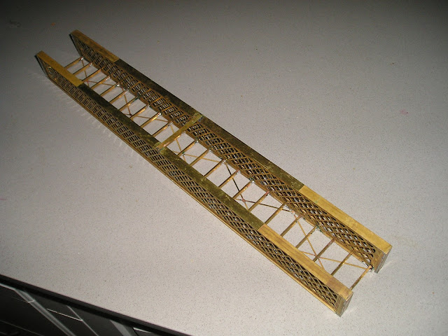
The above picture shows 2 spans of the 4 span bridge. Each span is 159 feet in length (approx 48 metres). I would have liked to scan this picture, and other detail shots, but I got a bit lazy
The bridge was built in 1878 as part of the extension of the main southern railway from North Wagga (Bomen) to Albury. The design was relatively common in NSW, as this was one of 18 bridges built to the John Whitton design. The Whitton bridge over the Murray River at Albury is still in use - which is testimate to the design able to carry todays trains.
The original design featured lattice truss arches to tie the 2 lattice beams together. However, the Wagga bridge was strengthened, and substantial support girders were added, and the arches removed
In 2001, under the Uneek range, a kit of the Whitton truss was offered. These were very expensive kits ($330) per span, with the piers an extra $25 per pair. I was very fortunately to buy 2 kits, as I have been reliably informed only 15 kits were ever made.. The instructions though were very poor - recommending glue for instance, and for the most part I devised my own construction sequence
First step was to solder the special brass shapes to the upper and bottom chord
After drilling out the holes for the interconnecting pin (0.55mm - not the 0.3mm that the kit instructions states), one can then solder one of the chords to the sides
Taking inspiration from the old pencil case design, I slid in the second lattice side, and soldered the other chord to the side. The lattice sides do not line up, and 1 mm has to be removed (this is also stated on the instructions - which might be a way of saying there was a drafting error on the etches)
Solder one of the ends to the girder. Note that there is an unetched section on the chord - this is a detail, for a strengthening plate on the real bridge - and the kit has another rivet piece to cover this. I have chosen to not add them at this stage.
Painting of the girders is a problem that I solved AFTER I built the first pair. After sliding the girder side out, clean the inside, and PAINT. I happened to use a rattle can of black on hand
Once the paint had dried, slide the sides together, and solder on the other girder end. Fit the pins, solder and cut off.
Build a second lattice. Yes, this bridge is fairly repetitive
Join the 2 lattice beams with the supplied "I" girders. The first kit had only 23 "I" girders, and whilst the instructions said 23, the plans had a spacing diagram for 25. My second kit had 25 "I" beams. Annoying. Fit the angle irons to the base.
Anyway, when you have struggled with the spacing, you will end up with a 159 foot span. The kit has the lattice arches to tie the spans sides together and give strength, but this style was not for my time frame. I used a piece of brass strip to do the same thing for now, and this will be removed later. The area that I have used for the strip will be covered with the rivet overlay I mentioned previously,
Once you have built one span - REPEAT for the second span. Just as well, I don't have more than 2 spans, as I would have gone crazy. Note one of the piers is bolstered up on a plinth - yes, it was shorter than the rest - but buried in the riverbank, it will be OK.
Further progress is awaiting the external girders. Not sure if I will use ABS (has been ordered), or brass - the latter is preferred, but I have not yet been able to locate a source for the sizes I need.


Nice work Rob! The bridge is going to look amazing.
ReplyDelete